
Product Overview


6/18
Siem ens Electrohydraulic actuators for valves CM1N4561en
Building Technologies 2014-06-18
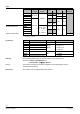
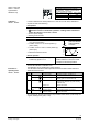
Direction of
operation
Sequence control
or stroke limit control
Control signal Y
Position feedback U
Flow characteristic
ON
reverse-
acting
Sequence control
Signal addition
QAF21../QAF61..
DC 4...20 mA lin = linear
OFF *
direct-
acting
Stroke limit
control
DC 0 ...10 V
log = equal
percentage
* Factory settings: all
switches OFF
Relationship
between control
signal Y and
volumetric flow
0
4
l
i
n
l
o
g
V
100
V
0
10 V
20 mA
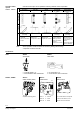
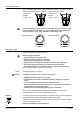
· With normally-closed valves, «direct-acting» means that with a signal input of 0 V,
the valve closes (applies to all Siemens valves listed under
«equipment combinations» on page 3)
· With normally-open valves, «direct-acting» means that with a signal input of 0 V, the
valve is open.
Direct acting Reverse-acting
(10 V)
100 %
0 %
Y
(10 V)
100 %
0 %
Y
100 %
Y
Stroke
0 %
D
i
r
e
c
t
R
e
v
e
r
s
e
-
a
c
t
i
n
g
0 V
4 mA
0
W
10 V
20 mA
1000
W
Input DC 0...10 V
DC 4...20 mA
0...1000 W
Input DC 10...0 V
DC 20...4 mA
1000...0 W
The mechanical spring-return function is not affected by the direction of operation
selected.
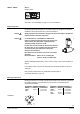
Setting the stroke limit control Setting the sequence control
The rotary switches LO and UP can be used
to apply an upper and lowe
r limit to the stroke in
increments of 3%, up to a maximum of 45%
The rotary switches LO and UP can be used
to determine the starting point or the operating
range of a sequence.
Position
of LO
Lower stroke
limit
Position
of UP
Upper stroke
limit
Position
of LO
Starting point for
sequence control
Position
of UP
Operating range
of sequence
control
0
0 %
0
100 %
0
0 V
0
10 V
1
3 %
1
97 %
1
1 V
1 10 V *
2
6 %
2
94 %
2
2 V
2 10 V **
3
9 %
3
91 %
3
3 V
3 3 V ***
4
12 %
4
88 %
4
4 V
4
4 V
5
15 %
5
85 %
5
5 V
5
5 V
6
18 %
6
82 %
6
6 V
6
6 V
7
21 %
7
79 %
7
7 V
7
7 V
8
24 %
8
76 %
8
8 V
8
8 V
9
27 %
9
73 %
9
9 V
9
9 V
A
30 %
A
70 %
A
10 V
A
10 V
B
33 %
B
67 %
B
11 V
B
11 V
C
36 %
C
64 %
C
12 V
C
12 V
D
39 %
D
61 %
D
13 V
D
13 V
E
42 %
E
58 %
E
14 V
E
14 V
F
45 %
F
55 %
F
15 V
F
15 V
* Operating range of QAF21.. (see below)
** Operating range of QAF61.. (see below)
*** The smallest adjustment is 3 V; control with 0…30 V is only possible via Y.
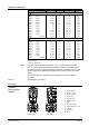
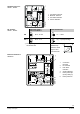
DIL switches
SKD62UA
Selection of direction of
operation
SKD62UA
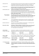
Note
Stroke limit control
and sequence control
SKD62UA