
Product Overview


4/18
Siem ens Electrohydraulic actuators for valves CM1N4561en
Building Technologies 2014-06-18
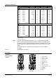
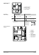
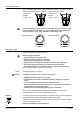
The hydraulic pump (6) forces oil from the suction chamber (3) to the pressure chamber
(8) and thereby moving the pressure cylinder (2) downwards. The valve stem (11)
retracts and the valve opens. Simultaneously the return spring (4) is compressed.
Activating the solenoid valve (5) allows the oil in the pressure chamber to flow back into
the suction chamber. The compressed return spring moves the pressure cylinder
upwards. The valve stem extends and the valve closes
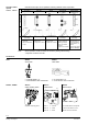
Turning the manual adjuster (1) clockwise moves the pressure cylinder downwards and
opens the valve. Simultaneously the return spring is compressed.
In the manual operation mode the control signals Y and Z can further open the valve
but cannot move to the «0%» stroke position of the valve. To retain the manually set
position, switch off the power supply or disconnect the control signals Y and Z. The red
indicator marked «MAN» is visible.
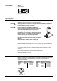
When setting the controller for a longer time period to manual operation, we
recommend adjusting the actuator with the manual adjuster to the desired position. This
guarantees that the actuator remains in this position for that time period. Attention: Do
not forget to switch back to automatic operation after the controller is set back to
automatic control.
Turn the manual adjuster counterclockwise to the end stop. The pressure cylinder
moves upward to the «0%» stroke position of the valve. The red indicator marked
«MAN» is no longer visible.
The actuator can manually be adjusted to a stroke position > 0 % allowing its use in
applications requiring constantly a minimal volumetric flow.
The SKD32.51, SKD32.21, SKD82.51.. and SKD62.. actuators, which feature a spring-
return function, incorporate an additional solenoid valve which opens if the control
signal or power fails. The return spring causes the actuator to move to the
«0 %» stroke position and closes the valve.
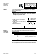
The actuator is controlled by a 3-position signal either via terminals Y1 or Y2 and
generates the desired stroke by means of above described principle of operation.
· Voltage on Y1 piston extends valve opens
· Voltage on Y2 piston retracts valve closes
· No voltage on Y1 and Y2 piston / valve stem remain in the respective position
The valve is either controlled via terminal Y or override control Z. The positioning signal
Y generates the desired stroke by means of above described principle of operation.
· Signal Y increasing: piston extends valve opens
· Signal Y decreasing: piston retracts valve closes
· Signal Y constant: piston / valve stem remain in the respective position
· Override control Z see description of override control input, page 8
A frost protection thermostat can be connected to the SKD6.. actuator. The added
signals from the QAF21.. and QAF61.. require the use of SKD62UA actuators. Notes
on special programming of the electronics are described under «Enhanced electronics»
on page 5.
«Connection diagrams» for operation with frost protection thermostat or frost protection
monitor refer to page 14.
Opening the valve
Closing the valve
Manual operation mode
Note: Controller in
manual operation
Automatic mode
Minimal volumetric flow
Spring-return facility
SKD32../SKD82..
3-position control signal
SKD62.., SKD60..
Y control signal
DC 0...10 V and/or
DC 4...20 mA, 0…1000 Ω
Frost protection monitor
Frost protection
thermostat