
Product Overview


5/18
Siemens Electrohydraulic actuators for valves CM1N4566en
Building Technologies 2014-05-26
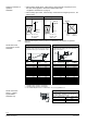
A frost protection thermostat can be connected to the SKC6.. actuator. The added
signals from the QAF21.. and QAF61.. require the use of SKC62UA actuators. Notes
on special programming of the electronics are described under «Enhanced electronics»
on page 5.
«Connection diagrams» for operation with frost protection thermostat or frost protection
monitor refer to page 16.
4
5
6
7
Z
0
3
Calib.
Status
ok
calib.
error
valve
jam
green
red
Status
Calib.
0.. .10V
4...20mA
Z
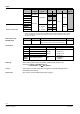
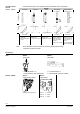
1 Connection terminals
2 Mode DIL switches
3 LED status indication
4 Slot for calibration
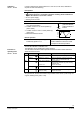
Positioning signal Y
Position feedback U
Flow characteristic
ON
ON
1 2
4567Z05
DC 4…20 mA
ON
21
4567Z07
lin = linear
OFF *)
ON
1 2
4567Z06
DC 0…10 V
ON
21
4567Z08
log = equal percentage
*) Factory setting:
All switches OFF
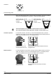
Relationship
between control
signal Y and
volumetric flow
0
4
l
in
l
o
g
V
100
V
0
10 V
20 mA
Calib.
Sta tus
ok
calib.
error
val ve
jam
green
red
Status
Calib.
0...10V
4...20mA
Z
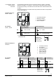
1 Connection terminals
2 DIL switches
3 LED status indication
4 Stroke calibration
5 Rotary switch Up
(factory setting 0)
6 Rotary switch Lo
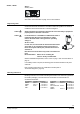
Direction of operation Sequence control
or stroke limit control
Control signal Y
Position feedback U
Flow characteristic
ON reverse-acting
Sequence control
Signal addition
QAF21../QAF61..
DC 4...20 mA lin = linear
OFF * direct-acting Stroke limit control DC 0...10 V
log = equal
percentage
*
Factory settings: all switches
OFF
Relationship
between control
signal Y and
volumetric flow
0
4
l
i
n
l
o
g
V
100
V
0
10 V
20 mA
Frost protection monitor
Frost protection
thermostat
Standard electronics
SKC62.., SKC60
DIL switches
SKC62.., SKC60
Enhanced electronics
SKC62UA
DIL switches
SKC62UA