4 Electrohydraulic actuators for valves with a 40 mm stroke 566 SKC32.. SKC82.. SKC62.. SKC60 · SKC32.. Operating voltage AC 230 V, 3-position control signal · SKC82.. Operating voltage AC 24 V, 3-position control signal · SKC6.. Operating voltage AC 24 V, control signal DC 0…10 V, 4…20 mA or 0...1000 Ω · SKC6..
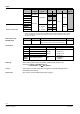
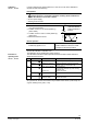
Types Type Standard electronics Enhanced electronics SKC32.60 AC 230 V SKC32.61 2) SKC82.60 SKC82.60U * SKC82.61 SKC82.61U * AC 24 V SKC62 2) SKC62U * SKC60 SKC62UA * 1) 2) * TÜV tested as per DIN EN 14597 Operating voltage Positioning signal Spring-return Positioning time Enhanced Function Time Opening Closing functions yes 18 s 3-position 120 s DC 0...10 V, 4...20 mA, or 0...
Equipment combinations Valve type DN 3 PN-class kvs [m /h] data sheet Two-port valves VV... (control valves or safety shut-off valves)): VVF21... 1) Flange 100 6 124…160 4310 Flange 100 6 160 4401 Flange 100…150 10 124…315 4320 Flange 100…150 10 160…400 4402 Flange 100…150 16 124…315 4330 Flange 100…150 16 125…400 4403 1) Flange 65…150 16 49…300 4340 1) Flange 65…150 16 49…300 4345 VVF43.. Flansch 65…150 16 50…400 4404 VVF53..
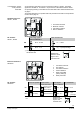
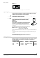
Opening the valve The hydraulic pump (6) forces oil from the suction chamber (3) to the pressure chamber (8) and thereby moving the pressure cylinder (2) downwards. The valve stem (11) retracts and the valve opens. Simultaneously the return spring (4) is compressed. Closing the valve Activating the solenoid valve (5) allows the oil in the pressure chamber to flow back into the suction chamber. The compressed return spring moves the pressure cylinder upwards.
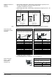
A frost protection thermostat can be connected to the SKC6.. actuator. The added signals from the QAF21.. and QAF61.. require the use of SKC62UA actuators. Notes on special programming of the electronics are described under «Enhanced electronics» on page 5. «Connection diagrams» for operation with frost protection thermostat or frost protection monitor refer to page 16. 4567Z03 Frost protection monitor Frost protection thermostat Standard electronics SKC62.., SKC60 Calib. Z 1 2 3 4 Status ok 0...10V 4.
Selection of direction of operation SKC62UA · With normally-closed valves, «direct-acting» means that with a signal input of 0 V, the valve closes (applies to all Siemens valves listed under «equipment combinations» on page 3) · With normally-open valves, «direct-acting» means that with a signal input of 0 V, the valve is open. Direct acting Reverse-acting g Input DC 0...10 V DC 4...20 mA 0...
Calibration SKC62.., SKC60 In order to determine the stroke positions 0 % and 100 % in the valve, calibration is required on initial commissioning: Prerequisites · Mechanical coupling of the actuator SKC6.. with a Siemens valve · Actuator must be in «Automatic operation» enabling stroke calibration to capture the effective 0 % and 100 % values · AC 24 V power supply · Housing cover removed Calibration 01124 0% 1 3 2 4567Z09 green LED flashes; position feedback U inactive Stroke 1.
Override control input can be operated in following different modes of operation Override control input Z SKC62..
SKC62.., SKC60 ASC1.6 auxiliary switch switching point 0…5 % stroke See section «Technical data» on page 12 for more information. Engineering notes Caution Safety regulations and restrictions designed to ensure the safety of people and property must be observed at all times! Caution For media below 0 °C the ASZ6.5 or ASZ6.6 stem heater is required to keep the valve from freezing. For safety reasons the stem heater is designed for an operating voltage of AC 24 V / 30 W.
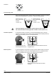
Orientation 90° 90° Commissioning notes When commissioning the system, check the wiring and functions, and set any auxiliary switches and potentiometers as necessary, or check the existing settings. Cylinder with valve stem connector fully retracted à stroke = 0% 0 0 1 4566Z13 4566Z12 1 Cylinder with valve stem connector fully extended à stroke = 100 % The manual adjuster must be rotated counterclockwise to the end stop. This causes the Siemens valves, types VVF.. and VXF..
Maintenance notes The SKC.. actuators are maintenance-free. When servicing the actuator: · Switch off pump of the hydronic loop · Interrupt the power supply to the actuator · Close the main shutoff valves in the system · Release pressure in the pipes and allow them to cool down completely · If necessary, disconnect electrical connections from the terminals · The actuator must be correctly fitted to the valve before recommissioning. Repair Recommendation SKC6..: trigger stroke calibration.
Technical data SKC6.. AC 24 V –20 % / +30 % SELV / PELV Frequency 50 or 60 Hz Max. Power consumption at SKC32.60: SKC82.60, ..60U SKC60 50 Hz 18 VA / 14 W 15 VA / 12 W 17 VA / 13 W SKC32.61: SKC82.61, ..61U SKC62.. 24 VA / 18 W 19 VA / 14 W 21 VA / 15 W External supply cable fuse min. 0.5 A, slow min. 1.6 A, slow max. 6 A, slow max. 10 A, slow Signal inputs Control signal DC 0...10 V, 3-position DC 4...20 mA, 0...
SKC82..U UL 873 SKC62U, UL873 SKC62UA C-tick N474 N474 Environmental compatibility ISO 14001 (Environment) ISO 9001 (Quality) SN 36350 (Environmentally compatible products) RL 2002/95/EG (RoHS) Dimensions refer to «Dimensions», page 17 Weight (packing excluded) SKC32.60 9.80 kg SKC82.60 9.80 kg SKC60/62 9.85 kg SKC82.60U 10.10 kg SKC62U/UA 10.15 kg SKC32.61 9.85 kg Conform with UL standards Dimensions / Weight SKC82.61 9.85 kg SKC82.61U 10.
Accessories ASC1.6 Auxiliary switch ASC9.3 double auxiliary switch ASZ7.3 Potentiometer ASZ6.5 stem heater ASZ6.6 stem heater SKC32.., SKC82.. SKC6.. Switching capacity Switching capacity per auxiliary switch AC 24 V, 10 mA...4 A resistive, 2 A inductive AC 250 V, 6 A resistive, 2.5 A inductive Change in overall resistance of potentiometer at nominal stroke min. current in sliding contact expected lifetime max.
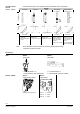
Internal diagrams SKC32.61 AC 230 V, 3-Position Cm1 end switch n solenoid valve for springreturn c1, c2 ASC9.3 double auxiliary switch a, b, c ASZ7.. potentiometer Y1 Positioning signal «open» SKC32.60 AC 230 V, 3-Position Y2 Positioning signal «close» 21 spring-return function N neutral conductor SKC82.61 AC 24 V, 3-Position Cm1 end switch n solenoid valve for springreturn c1, c2 ASC9.3 double auxiliary switch a, b, c ASZ7.. potentiometer SKC82.
Connection diagrams SKC32.. AC 230 V 3-Position SKC32.61 F1 N1, N2 Y1, Y2 SKC82.. AC 24 V 3-Position temperature limiter controller actuators SKC82.61, SKC82.61U F1 temperature limiter N1, N2 controller Y1, Y2 actuators SKC6.. AC 24 V DC 0…10 V, 4…20 mA, 0…1000 Ω SKC32.60 L N Phase neutral Y1 Y2 21 Positioning signal «open» Positioning signal «close» Spring-return function SKC82.60, SKC82.
SKC62 SKC62U SKC62UA Y1 N1 F1 F2 F3 F4 G (SP) actuator controller temperature limiter frost protection thermostat terminals: 1 – 2 frost hazard / sensor is interrupted (thermostat closes with frost) 1 – 3 normal operation temperature detector Frost protection monitor with 0…1000 Ω signal output, e.g. QAF21.. or QAF61..
Replacement parts Order numbers for replacement parts Actuator type SKC32.60 SKC32.61 SKC82.60 SKC82.60U SKC82.61 SKC82.