
User Guide


Flowrite EA 599 Series SKB/C/D 62UA Electronic Valve Actuator Advanced Features Technical Instructions
Document Number 155-717
July 11, 2011
Siemens Industry, Inc. Page 7
Mounting and
Installation
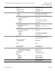
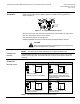
The vertical position is the recommended position for mounting and the only position for
NEMA Type 3R rating with the Weather Shield. Acceptable mounting positions are
shown in
Figure 10.
EA0133R2
Not allowed with the
Weather Shield
Not allowed in
any circumstance
Figure 10. Acceptable Mounting Positions.
Allow four inches (100 mm) around the sides and back of the actuator and eight inches
(200 mm) above and to the front of the actuator.
See dimensions in Figure 23 and Figure 24.
Detailed installation instructions for field mounting are shipped with the actuator.
CAUTION:
When removing the knockout do not damage the circuit board. Use
the top knockout position, if possible.
Check the wiring for proper connections.
Start-up
NOTE: The valve body assembly determines the complete assembly action.
Spring Return
Function
All SKB/C/D62UA actuators are factory-fitted with a spring-return function. If the control
signal or power supply fails, the actuator will return to the 0% stroke position (stem fully
retracted).
Start-up,
Continued
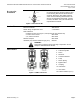
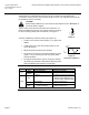
The override control input (Z) has three modes of operation:
U
Z
G
G0
Y
M
100 %
Y
H
min
Stroke
H
max
U
Z
G
G0
Y
M
R
100 %
R []
0 %
Stroke
50 900
Z-Contact not Wired
Valve Stroke Follows Control Signal Y
Z-Contact Connected to M Via Resistor R
Linear or Equal-Percentage Characteristic
Starting Position at 50 / End Position at 900
Y-Input has No Effect
U
Z
G
G0
Y
M
100 %
Y
Stroke
V
max
0 %
U
Z
G
G0
Y
M
100 %
Y
Stroke
V
max
0 %
Z-Contact Connected Directly to G
Y-Input has No Effect
Z-Contact Connected Directly to G0
Y-Input has No Effect
No Function
Actuator Fully Extended
Override with 0 ... 1000
Actuator Fully Retracted
EA1064R1
Override Control
NOTE: The Z-modes have a "direct acting" factory setting.