
Installation Instructions

Document No.129-368
Installation Instructions
September 25, 2018
Page 6 of 8 Siemens Industry, Inc.
Wiring
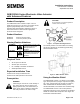
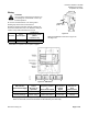
Figure 24. Wiring Diagram.
Connecting Terminals
24 Vac
G
System Potential (SP)
G0
System Neutral (SN)
Y
Control Input: 0 to 10 Vdc or 4 to 20 mA
(DIP switch selectable)
Z
Override Input
(See Technical Instructions 155-717)
M
Measuring Neutral
U
Position Indicator: 0 to 10 Vdc or
4 to 20 mA
The position output signal U will switch from 0 to 10 Vdc
to 4 to 20 mA when a 4 to 20 mA input signal is selected
and used on the terminal.
Start-Up
• Check the wiring for proper connections.
• Consult the Flowrite 599 Series SKB/C/D 62UA
Series Electronic Valve Actuator 24 Vac
Proportional Control Advanced
FeaturesTechnical Instructions 155-717 for
detailed commissioning instructions.
Stroke Calibration
To determine the stroke positions 0 and 100% in the
valve, calibration is required when the valve/actuator are
commissioned for the first time.
The actuator must be mechanically connected to a valve
and must have a supply voltage of 24 Vac. The
calibration procedure can be repeated as often as
necessary.
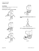
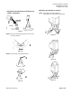
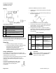
To initiate the calibration procedure, short
circuit the contacts inside the slot located
on the printed circuit board (with a
screwdriver).
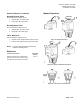
Automatic calibration proceeds as follows:
• Actuator runs to the 0 stroke position (1) the green
LED flashes .
• Actuator then runs to the 100% stroke position (2)
the green LED flashes.
• Measured values are stored in the EPROM.
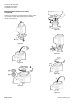
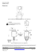
• The actuator now moves to the position defined by
control signal Y or Z (3), and the green LED now
glows steady (normal operation)
• Throughout this procedure, output U is inactive,
meaning the values only represent actual positions
when the green LED stops flashing and remains
on continually.
Table 1. LED Status.
LED
Display
Function
Action
Green
ON
Normal Operation
Automatic operation
Flashing
Stroke calibration
In Progress
Wait for calibration to be
completed (LED stops
flashing)
Red
ON
Faulty stroke
calibration
Internal Error
- Check mounting
- Restart stroke
calibration (by short-
circuiting calibration slot)
- Replace electronics
Flashing
Inner valve jammed
Check the valve
OFF
• No power
supply
• Faulty
electronics
-Check mains
-Replace electronics
CAUTION:
Before starting calibration, be sure that the
manual adjuster is set to Automatic to
register the actuator values.