
Installation Instructions

Document Number: 129-368
Installation Instructions
September 25, 2018
Siemens Industry, Inc. Page 5 of 8
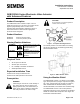
Wiring
CAUTION:
Use care when removing the knockout. Do
not damage the circuit board. Use the top
knockout position.
Do not use autotransformers. Use earth ground
isolating step-down Class 2 transformers.
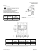
Determine supply transformer rating by summing the
total VA of all actuators used. The maximum rating for
a Class 2 step-down transformer is 100 VA.
Actuator
Power
Consumption
Actuators per
Class 2 Supply Circuit*
(80% of
transformer VA)
SKB62UA
17 VA
4
SKC62UA
28 VA
2
*Operating more actuators requires additional
transformers or separate 100 VA power supplies.
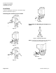
Figure 22.
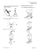
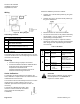
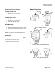
Wiring for SKB/C62UA is shown in Figure 23
and Figure 24.
1
2
3
4
Figure 23. SKB/C62UA.
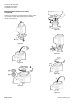
DIP Switches
(From Left to Right)
1
Select
Direction of
Operation
2
Sequence Control
or
Stroke Limit Control
3
Selection of
Control
Signal
4
Selection of
Flow
Characteristic
ON
Reverse-acting
Sequence control
4 to 20 mA
Modified*
OFF
(Factory Settings)
Direct-acting
Stroke limit control
0 to 10 Vdc
Default
*Changing the default setting will modify an equal percentage valve to a linear flow characteristic.
When set to Default, the flow characteristic is determined by the valve body.