
Data Sheet for Product


Flowrite 599 Series SKB/C/D 62UA Electronic Valve Actuator Advanced Features Technical Instructions
Document Number 155-717
September 25, 2018
Siemens Industry, Inc. Page 13
Wiring
Do not use auto-transformers. Use earth ground isolating step-down Class II power
supplies.
Determine supply transformer rating by summing total VA of all actuators used.
Determine the rating for Class 2 step-down transformer is 100 VA and consider the
following requirements:
SKB62UA = 17 VA SKC62UA = 28 VA SKD62UA = 17 VA;
A maximum of four actuators can be powered by one transformer (80% of transformer
VA). Operating more than four SK series actuators requires additional transformers or
separate 100 VA power supplies.
The position output signal U will switch from 0 to 10 Vdc to 4 to 20 mA when a 4 to
20 mA input signal is selected and used on the Y terminal.
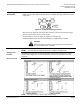
Wiring Diagrams
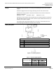
Figure 19. Terminal Connections.
24 Vac
G
System potential (SP)
G0
System neutral (SN)
Y
Control input signal 0 to 10 (30) Vdc or 4 to 20 mA
M
Measuring neutral
U
Position indication 0 to 10 Vdc or 4 to 20 mA (see Table 1)
Z
Override input.
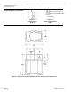
Figure 20. Auxiliary Switches.
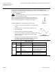
Table 1. Actuator Output Signal U.
Actuator Input Signal
Receiving Impedance
Low
(<500 ohm)
High
(>10K ohm)
0 to 10 Vdc
0 to 20 mA
0 to10 Vdc
4 to 20 mA
4 to 20 mA
2 to 10 Vdc