
User's Manual

2-21
1010NFM-3J
Section 2
NOTE: Before preceeding to mount transducers, it is recommended that Section 3 - HARD-
WARE INSTALLATION GUIDE be reviewed. Refer to the Pick/Install Xdcr menu and
menu structure shown below for menu cell descriptions and details.
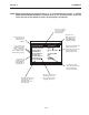
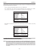
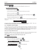
Scroll List and select desired Model
Pick/Install Xdcr
Transducer Model 1011 Universal
Transducer Size B3
Xdcr Mount Mode Reflect
Spacing Offset Spacer Bar PB-1
Number Index 0
Spacing Method Track 1012TAH
Ltn Value (in) 0.565
Install Complete? No
Empty Pipe Set MTYmatic
Zero Flow Adjust Actual Zero
Siemens 2 Channel [1] FLOW1
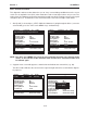
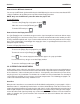
This menu cell
shows the actual
spacing distance
required between
the transducers.
Use this menu cell to
select the type of
transducer to be
installed.
This menu cell
allows you to select
a mounting mode.
*Use Reflect Mode
whenever possible.
A
fter the transducers are
operating, you can use
this menu cell to
manually set the zero
flow correction.
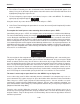
These menu cells
identify the spacing
indices on the spacer
bar. You must use
these settings to mount
the transducer properly.
This menu cell indicates the
model number of the
appropriate spacer bar for
your transducers and
spacing requirements.
Once you select the
type, use this menu
cell to specify the
transducer size.
Use this menu cell to
inform the meter that you
have completed the
transducer mounting.
After the transducers are
operating, you can use
this menu cell to set the
empty pipe threshold.