
User's Manual

2-20
1010NFM-3JSection 2
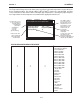
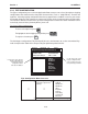
2.4 THE PICK/INSTALL XDCR MENU
Use this menu after creating a new site setup in the Channel Setup menu, and defining the pipe
parameters in the Pipe Data menu.
Based on pipe data (and optionally application data) entries, the Pick/Install Xdcr menu automatically
identifies the most suitable transducers for the application. It recommends the appropriate mounting
mode (direct or reflect) and lists the Spacer Bar or Mounting Track part number and spacing index.
Ideally, you will be able to use the primary recommendations. However, you can edit the menu entries
as required to accommodate different transducers or mounting configurations.
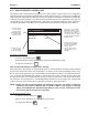
The flow computer will adjust its parameters to optimize performance based on your selections. The
Ltn menu cell shows the required spacing distance (in inches or millimeters) between the upstream
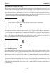
and downstream transducers. Use the [Install Completed?] menu cell to inform the flow computer that
you completed the physical mounting of the transducers. You can define the empty pipe and zero flow
values once the transducers are operational.
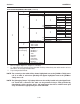
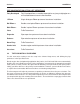
PIPE CONFIGURATION OPTION LIST DEFINITIONS
Fully Developed Fully Developed flow, as would be expected for very long straight pipe runs
or installation downstream of a flow condition.
1 Elbow Single 90 degree Elbow upstream of transducer installation.
Dbl Elbow + Double out-of-plane Elbows upstream of transducer installation.
Dble Elbow - Double in-plane Elbows upstream of transducer installation.
Valve To Be Determined.
Expander Pipe expansion upstream of transducer installation.
Reducer Pipe reduction upstream of transducer installation.
Norm Entry To Be Determined.
Header Inlet Header or pipe manifold upstream of transducer installation.
Intrusions To Be Determined.