
User's Manual

2-19
1010NFM-3J
Section 2
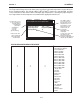
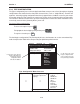
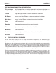
2.3.4 PIPE CONFIGURATION
The [Pipe Configuration] menu cell in the Application Data menu presents a list of descriptions of piping
configurations that could affect the flow profile characteristics (such as “Single Elbow”). Examine the
option list. Selecting a piping configuration that closely approximates conditions at or near your mount-
ing location allows the flow computer to compensate for the effect of upstream piping on flow profile.
The number of diameters between the upstream configurations and the transducer installation can be
numerically entered via the [Anomaly Diams] menu cell.
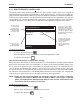
To select a Piping Configuration:
To access the option list press
To highlight the desired piping configuration press
To register selection press
ENT
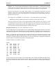
The default pipe configuration (Fully Developed) wll cause the flowmeter to use the conventional Rey-
nolds Compensation Table when compensating for liquid flow profile behavior.
Application Data Pipe Configuration Fully Developed*
(Change to Upstream 1 Elbow
Piping) Dbl Elbow +
Dbl Elbow -
Valve
Expander
Reducer
Norm Entry
Header Inlet
Intrusions
Anomaly Diams xxxx (numeric entry)
Pipe Configuration Menu Structure
* Default
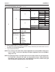
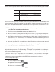
Siemens Dual Path [1] Path 1
Disignate Pipe Shape Near Transducers
Liquid Class Water 20C/68F
UniMass Table Create/Edit Table
Temperature Range -40F to 250F
Pipe Configuration Fully Developed
Anomaly Diams 1 Elbow
Dbl Elbow +
Dbl Elbow -
Valve
Expander
Reducer
Norm Entry
Header Inlet
Intrusions
Application Data
Use this menu cell to enter the
number of pipe diameters
between the upstream
configuration and the
transducer installation.
Use this menu cell to select
the pipe configuration that
most accurately represents
the upstream pipe condition.