
User's Manual

1-16
1010NFM-3JSection 1
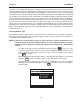
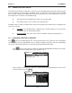
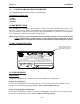
Next, we will pick the pipe size: [1CS80] by moving the cursor to the selection and then press-
ing . This is all there is to setting up the pipe parameters.
Now, we will select and install the transducers.
ENT
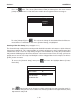
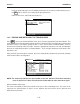
1.8.2 PICKING AND INSTALLING THE TRANSDUCERS
Press to access the Pick/Install Xdcr menu, then select the appropriate Transducer Model. The
meter then analyzes your pipe data and registered transducer list before calculating the recommended
transducer size(s). The top-line prompt shows a series of transducer recommendations, that are
listed in order of priority from left to right. Select the appropriate transducer size with consideration
given to the computed transducer recommendations. In the example below we will install the “B3”
transducer size.
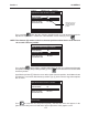
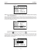
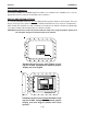
After you make your transducer selection, the meter automatically computes the preferred mounting
mode and transducer spacing index.
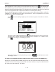
Note the Number Index value.
This value corresponds to the index marked on the spacer bar or mounting track. The value of Ltn
represents the actual distance in inches or mm, between the front surfaces of the upstream and
downstream transducers.
NOTE: The meter only indicates the part number of the 1011 Universal Transducer mounting
track or spacer bar. It does not indicate this information for other transducer types.
Siemens
Siemens