
User's Manual

6-4
1010NFM-3JSection 6
6.3 HOW TO SET UP SYSTEM 1010 FOR FLOW TUBE OPERATION
The example in this section shows how to set up channel 1 of a 1010 dual channel system for use with
a 1011FT stainless steel Flow Tube. Note that Series 1010 dual-channel models allow flow tube opera-
tion with either measurement channel. In addition, all 1010 flow computers operate with both 1011FT
and 992DFT series of flow tubes. This example begins at the Channel Setup Menu. If necessary,
review paragraph 1.7.3 for instructions on how to select a Meter Type and a measurement channel.
6.3.1 OVERVIEW
Setting up the measurement channel for Flow Tube operation consists of the following tasks:
• Select a Meter Type (in this case Dual Channel Flow).
• Select a channel to install the flow tube (e.g., Channel 1).
• Set Kc calibration (slope correction) indicated on Flow Tube tag. (Note: Programmed Kc
must match offset error on plastic Kc tag to get accurate flow tube readings. See paragraph
2.7.3 Calibrate Flow Rate.)
• Create a site setup to store the flow tube installation parameters.
• Enter liquid Parameters (optional, default = water@68
°F).
• Complete the Flow Tube install procedure.
6.3.2 SETUP PROCEDURE
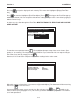
From the Channel Select screen, press to access the option list, then press to move the
cursor to [FlowTube] (if required).
To select Flow Tube press . This enables the Flow Tube menu. Press to access Channel
Setup menu.
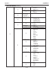
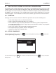
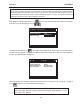
Channel 1 Clamp-on
Channel 2 >FlowTube
Reflexor
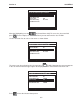
Siemens 2 Channel [1] Channel 1
Choose Channel 1 Flowmeter Type
Dual Channel Flow
ENT