
User's Manual

3-12
1010NFM-3J
Section 3
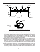
2. Place the track rail assembly on the top surface of the pipe at the location where you have deter-
mined it would be mounted. Ensure that it is a smooth area without any raised spots or seams.
Holding the assembly in place, loop one of the roller chains under the pipe, pull it around and main-
tain tension while slipping a link over the tension screw hook. Tighten the tension screw enough to
hold the assembly on the pipe, but still allow rotation. Repeat for the other roller chain. Rotate the
track rail assembly to the intended nine o’clock mounting position on the pipe, then tighten both
tension screws just enough to prevent rotation. Do not overtighten.
3. Mark a generous area around the transducers (1/2-inch on either side and half again the length front
and back) with a pencil or chalk. Loosen and move the assembly away from marked area. Prepare
the two areas you marked by de-greasing the surface, if needed, and removing any grit, corrosion,
rust, loose paint or surface irregularities with the abrasive pipe conditioning material provided. Clean
the pipe of all debris and abrasive particles.
4. Insert the index pin into the reference hole. Select a transducer, apply a thin band of couplant com-
pound to the transducer’s contact surface. Place the transducer between the track rails, slightly
behind the pin and under the clamping screw assembly. Slide it forward until it butts up firmly against
the reference pin.
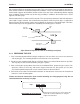
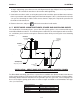
Flow
Î
Reference Pin
Shown Inserted
Chain Tension
Screw
Upstream
Transducer
Transducer
Clamping Screw
Downstream Xdcr
Roller
Chain
N
umber Index pi
n
Shown inserted
Track Rail
Assembly
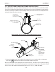
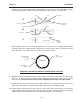
Chain Tension
Screw
Upstream
Transducer
Transducer
Clamping Screw
Downstream
Transducer
Roller
Chain
Number Index Pin
Shown Inserted
Track Rail
Assembly
Reference Pin
Shown Inserted
Flow Î
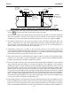
INSTALLATION - REFLECT MOUNT WITH MOUNTING TRACK
FRONT VIEW Ç
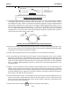
Chain
Tension
Screw
Loop Chain over
tension screw hook
Chain Tension
Screw
Loop Chain
over tension
screw hook