
User's Manual

3-11
1010NFM-3JSection 3
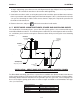
3.1.8 USING 1012T MOUNTING TRACKS
The 1012TP and 1012THP Mounting Tracks provide a rigid mounting platform for Series
1011 universal or high precision size A or B transducers. The mounting tracks service pipe sizes up to
a maximum of 5.00” (140 mm) outer diameter. Operating temperatures are supported up to 250°F
(121°C). The assembly consists of lightweight aluminum track rails with integral transducer clamping
screws. Attached index pins enable positive locating of the transducers at fixed spacing locations.
Roller-chains and tension screws secure the assembly to the pipe. The following instructions refer to
1011 universal transducers. Please refer to Engineering Drawing 1012TP-7 for reflect mounting of high
precision transducers and 1012THP-7 for direct mounting of high precision transducers.
The 1012T mounting tracks support both Direct and Reflect mounting modes. The flow computer
recommends the appropriate transducers, mounting track and mounting mode, based on the pipe
data entries. Refer to the instructions in paragraph 2.4 for details on the Transducer Installation proce-
dure. If necessary, review paragraphs 3.1.2 through 3.1.4 for details on how to select and prepare a
mounting location on your pipe.
Installing a 1012T Mounting Track in Reflect Mode
Paragraph 2.4 describes the Transducer Installation procedures that lead up to the automatic selection
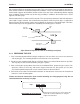
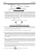
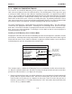
of transducers, mounting mode and spacing method. Examine the figure below, which shows a typical
Pick/Install Xdcr menu screen. Note the automatic assignment of model numbers for the transducer
and mounting track, plus the designation of the number index.
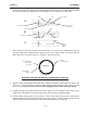
This example requires a Model 1012T Mounting Track to accommodate size B3 universal transduc-
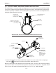
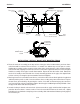
ers. Note the reported number index. You will be inserting an index pin into this hole on the track rail to
position one of the transducers (see diagram on next page).
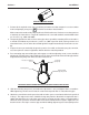
1. Perform all required menu steps up until the point where you respond to the [Install Completed?]
prompt. Note the reported number index. You will be inserting index pins into this hole and the
reference hole on the track rail (see diagram on next page). Check to ensure that you have a
matched set of transducers. They both should have the same S/N number but marked with either
an “A” or “B” (e.g., 100A and 100B).
Note selection of
type, size and
mounting mode.
Note selection of
mounting track part
number and number
index.
Siemens 2 Channel [1] SITE1
Key [Install] after mounting transducers
Pick/Install Xdcr
Transducer Model 1011 Universal
Transducer Size B3
Xdcr Mount Mode Reflect
Spacing Offset Minimum
Number Index 6
Spacing Method Track 1012TP
Ltn Value (in) 0.581
Install Completed? No
Empty Pipe Set Channel Not Setup
Zero Flow Adjust Channel Not Setup