
User's Manual

3-9
1010NFM-3JSection 3
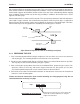
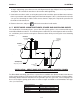
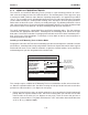
chalk) in the center of the tapered roller at the bottom of the frame (see “A” below). While holding,
also mark along the front edge of the frame with pencil or fine chalk line (see B below).
7. Disassemble the spacer bar and the unmounted frame. Use the bar as a straight edge and, with
one edge against the mounted frames tapered roller center and the other crossing the dot you
drew, draw a line crossing the dot (see “B” above). Set the bar aside.
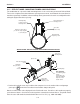
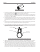
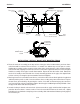
8. Wrap the mylar spacing guide around the pipe so that the left edge is against the transducer edge
mark (see “C” above). Arrange so that one end overlaps the other by at least three inches. Trim to
fit if necessary, but be sure not to trim at the overlapping end in order to keep it square.
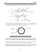
9. Realign left edge of the guide with the transducer edge mark. Line up both vertical edges of the
guide and ensuring that it is snug around the pipe, mark along the overlapping edge.
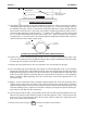
10. Remove Mylar spacing guide and lay it out on a flat surface. Either measure the exact distance
halfway between the overlap edge and the mark at the overlap, or fold the guide from the overlap
edge to overlap mark and draw a line at the fold or halfway point (see next page).
Transducer
Pi
p
e
Spacer Bar
Myla
r
Spacing
Guide
Transducer
Spacer Bar
Dot
Dot
Line
A
B
C
Transducer
Spacer Bar
Spacer Bar
Dot
Line
Transducer
Mylar
Spacing
Guide
Transducer
Edge Line
Transducer
Dot
Pipe
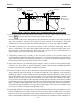
WRAPPING THE MYLAR SPACING GUIDE AROUND THE PIPE
E
ND VIEW
3" Overlapping
Edge
Mylar
Spacing Guide
Trim material from
inner edge if
necessary
Trim material from
inner edge if
necessary
3” Overlapping
Edge
Mylar
Spacing Guide
End View