
User's Manual

3-7
1010NFM-3JSection 3
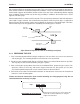
in Step 5. Sight along spacer bar to ensure axial alignment to the pipe. Adjust if necessary and do not
overtighten. Ensure that the transducers do not move while tightening.
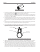
7.Connect the transducer cable, ensuring that you have observed the upstream/downstream orienta-
tion in respect to the cable and the input jack on the flow computer. If this is a dual-channel unit, make
sure you are connecting the cables to the correct channel’s input jacks. Repeat this procedure for
the number index transducer.
8.Return to the menu, and press to finish the transducer install routine.
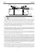
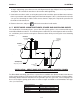
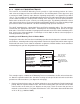
3.1.7 DIRECT MODE - MOUNTING FRAMES, SPACER BAR AND SPACING GUIDES
The combination of mounting frames, spacer bar and spacing guides is the recommended way to
mount Direct Mode transducers. The mounting frame establishes the axial alignment of the transduc-
ers, and allows you to remove and replace either transducer while preserving their exact mounting
location.
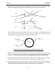
For Direct Mode mounting, you will use a spacer bar to establish the distance between transducers
and a spacing guide to easily locate the transducers at the nine o’clock and three o’clock positions.
Should the distance between transducers be beyond the span of a spacer bar, a measuring tape can
be used. The Mylar spacing guide comes in various lengths and widths to accommodate most pipe
sizes (see list below).
ENT
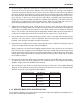
Spacing Guide P/N Size
1012-145-1A 2" x 26" (50.8 x 660.4 mm)
1012-145-1 2" x 45" (50.8 x 1143.0 mm)
1012-145-2 4" x 81" (101.6 x 2057.4 mm)
1012-145-3 4" x 155" (101.6 x 3937.0 mm)
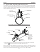
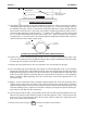
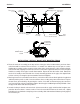
INSTALLATION - DIRECT MODE WITH TRANSDUCERS, MOUNTING FRAMES
SPACER BAR (Not Shown) AND SPACING GUIDE
Ltn
Transducer
Clamping
Scre
w
Mounting
Frame
Mounting
Strap
Ltn
Reference
N
otc
h
Mounting Strap
Adjusting Screw
Transducer
Clamping
Screw
Mounting
Frame
Mounting Strap
Adjusting Screw
Ltn
Reference
Notch
Mounting
Strap