
User's Manual

2-82
1010NFM-3JSection 2
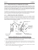
7. Access the [Pick/Install Xdcr] menu. Check the [Transducer Size] menu cell. If necessary, enter
the Xdcr Size option list and pick the transducer under test.
8. Check the [Xdcr Mount Mode] menu cell. Adjust to match the simulator chart above.
9. Move the highlight down to [Install Completed?] by pressing . Access the option list. To move
the cursor to [Install] press . Press to start the transducer install routine.
ENT
NOTE: Since Sizes A and C transducers are installed in Reflect Mode, you will see a pop-up
window that prompts you to: [Use Actual Zero]. You can ignore this by pressing the
<Down Arrow>.
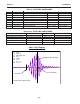
Upon the completion of the [Install] procedure, the flow computer should report a sonic velocity within
the range of approximately 1350m/s to 1700 m/s (depending on the transducer size under test). Next,
check [Diagnostic Data] menu. The [Valc %] item must be >35 for dependable operation. In addition,
note the reading, then compare it to the [Vfmax] item in the [Diagnostic Data/Site Setup Data] menu.
The value of the reading should be less than 2% of the published Vf max.
Confirming these values certifies that the entire system (computer, transducers, cables) is operating
correctly. The investigation should proceed to a review of all site conditions to locate the operating
problem.
4. Access the Installation Menu. Select [Meter Type] [Single, Dual or Quad Channel] depending on
meter type. Select the meter channel (1,2,3, or 4) depending on which measurement channel you
intend to test. Select [Clamp-On] and then [Channel Setup].
5. Access the [Channel/Path Setup] menu. Move the highlight to [Create/Name Site]. Create a new
Site Setup (e.g., TEST1). You can now enter data without altering an existing Site Setup.
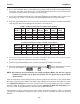
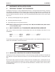
6. Select the [Pipe Data] Menu. Referencing either the English or metric pipe simulator chart below,
enter the pipe data corresponding to the transducer size under test.
Part Xdcr Pipe OD Pipe Wall Mount Spacing Number
Number Size (in.) Mat’l Thk (in.) Mode Offset Index
1012TB-1 A 0.650 Steel* 0.100* Reflect Nominal 7
1012TB-1 B 1.150 Steel* 0.100* Direct Minimum 4
1012TB-2 C 2.000 Steel* 0.100* Reflect Nominal 11
1012TB-2 D 3.500 Steel* 0.100* Direct Minimum Use Ltn
*System Defaults
1012TB-1 & 2 Universal Transducer Test Block Chart (English)
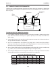
*System Defaults
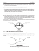
Part Xdcr Pipe OD Pipe Wall Mount Spacing Number
Number Size (mm) Mat’l Thk (mm) Mode Offset Index
1012TB1 A 16.5 Steel* 2.54* Reflect Nominal 7
1012TB1 B 29.2 Steel* 2.54* Direct Minimum 4
1012TB2 C 50.8 Steel* 2.54* Reflect Nominal 11
1012TB2 D 88.9 Steel* 2.54* Direct Minimum Use Ltn
1012TB-1 & 2 Universal Transducer Test Block Chart (Metric)