
User's Manual

2-81
1010NFM-3J
Section 2
2.11.8 TROUBLESHOOTING WITH TRANSDUCER TEST BLOCKS
To resolve an apparent system malfunction, you have to determine whether the problem is due to
equipment failure or an application condition. Our 1012 and 996 Transducer Test Blocks allow you to
bench test the flow computer, transducers and their cables. If the system operates properly using the
test block, then focus on application conditions as the source of the problem. Series A and B 1011
transducers use the 1012TB-1 Test Block and series C and D use the 1012TB-2 Test Block. At the
present time, neither one support the 1011 High Precision transducers.
The 996PSP-pipe simulator allows you test a 1010 series flow computer and 991 transducers from
size 0 to size 3. Note that although the 1010 flow computer operates with our 991 size 4 and 5 trans-
ducers, testing of these sizes with a 1010 flow computer is not currently supported.
2.11.9 USING THE 1012TB-1 AND 2 TEST BLOCKS
The 1012TB-1 and 1012TB-2 test blocks provide two test surfaces. Each surface supports a specific
transducer size. For example, one surface of the 1010TB-1 supports Size “A” transducers and the
other supports Size “B” transducers. The 1012 pipe simulators include two labels, one on each side-
plate. The labels identify the transducer size, data to be entered, and the surface to be used with the
specific transducer size. See drawing on next page.
1. Identify the side of the simulator that applies to the transducers under test. Rotate the clamping
bracket as required to mount transducers on the test surface.
2. Using a coupling compound (preferably CC-102), mount the transducers on the pipe simulator as
shown above. Slide each transducer until it presses against the pin-stop. Use the clamping screws
to hold the transducers in place.
3. Connect transducer cables between each transducer and the meter connectors for the channel
under test. The Up and Down orientation is not important.
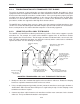
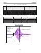
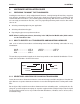
MOUNTING TRANSDUCERS ON A 1012 TRANSDUCER TEST BLOCK
Transducer clamping
screw
Transducer testing
surface for an A
size transducer
Slide transducers firmly against
Transducer Pinstops
Transducer
under test
Transducer
under test
Transducer
Clamping
Bracket
Example shows testing for
size B. Rotate brackets 180 to
mount SizeA transducers
This label shows the
data entry parameters
for size B. Size A
parameters appear on
a label on the other
side plate
This arrow points to
the surface associated with the
xdcr size identified on the label