
User's Manual

2-68
1010NFM-3JSection 2
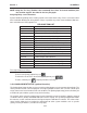
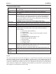
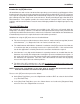
2.11.5 THE SITE SETUP DATA MENU
This menu provides data pertaining to transducer characteristics and operation. Some menu items
are for technical support interpretation only.
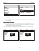
fx (drive) 30
N (burst length) 5
Ltn in -1.154
Vfmax GAL/MIN 1577.42
Vs max m/s 2165.41
Vs min m/s 936.62
Empty % 30
Samples/Cycle 16
Max Damping
Min Damping
HF 0.120
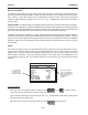
Siemens 2 Channel [1] Channel 1
Current transit drive code
Site Setup Data
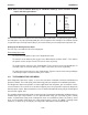
Temp 1 78.5
Temp 2 50.0
Reynolds # 318017
Specific Gravity 1.000 S.G.
Viscosity cP 1.000 cP
Pressure 14.5 PSIA
Viscosity cS 1.000 cS
Siemens 2 Channel [1] Channel 1
Current Reynolds number
Liquid Data
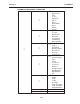
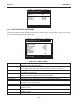
fx (drive) Current Transmit drive code selected during Initial Makeup. The drive code
controls the sonic transmit signal.
N (burst length) Transmit burst duration selected during Initial Makeup. To change N count
press <Right Arrow>. At equal sign enter numeric value (1 to 9 only).
Ltn (in/mm) Spacing distance between the transducers. It will be in inches or millimeters,
depending on default units.
Vfmax The flow velocity (in selected units) corresponding to one whole cycle offset
between upstream and downstream receive signals.
Vs max m/s Maximum correctly calibrated Vs for current transducer spacing.
Vs min m/s Minimum correctly calibrated Vs for current transducer spacing.
Empty % Value of Empty Alarm Setting. The meter will declare an empty status if signal
strength drops below this value.
Samples/Cycle Digital sampling rate.
Max Damping Maximum signal damping. Use to average digital data when an unstable
condition occurs.
Min Damping Minimum signal damping. Use to average digital data when an unstable
condition occurs.
HF Flow registration correction parameter.
SITE SETUP MENU ITEMS