
User's Manual

2-64
1010NFM-3JSection 2
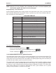
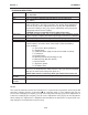
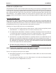
2.11.1 MAIN DIAGNOSTICS SCREEN
This is the Main Diagnostics Data screen. It provides menus that show Flow, Application, Liquid and
Site Setup information. The Test Facilities menu provides test/control functions to optimize operation,
analyze application conditions and to recover system operation.
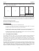
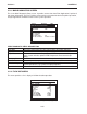
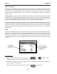
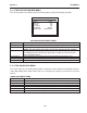
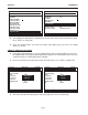
2.11.2 FLOW DATA MENU
This menu provides a “live” display of all flow-related output data.
Path Select All
Path Enable N/A
Flow Data
Application Info
Liquid Data
Site Setup Data
Test Facilities
Print Site Setup No
Date Site Created 04.18.01 13.24.01
Siemens Dual Path ABC
Real-time flow-related data
Diagnostic Data
Flow GAL/MIN -2.26
Flow Vel F/S -0.60
Total KGAL 0.0000
Vs m/s 1273.21
Signal mV 44
Valc % 57
Vaer % 0
Alarm Status ---R-----
AnCal GAL/MIN 0.0000
HiFlow GAL/MIN 1576.8
LoFlow GAL/MIN -1576.8
Siemens Quad Path SITE1
Current Flow Rate and Units
Flow Data
NOTE: Menu shows English units (i.e., gallons).
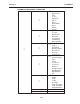
Flow Data This menu shows flow rate, total & alarm data; adjustable flow limits.
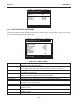
Application Info This menu shows current meter operating status.
Liquid Data This menu shows current Reynolds # and RTD temperature readings
(if this system includes optional RTD Temperature measurement cap-
ability).
Site Setup Data This menu shows current transducer setup data and signal status.
Test Facilities This menu provides system test and recovery routines.
Print Site Setup This Menu cell allows you to send an ASCII dump of the current Site Data to a
RS-232 port device (e.g. a printer or laptop computer).
Date Site Created This menu cell shows date and time when the current site was created.
MAIN DIAGNOSTIC MENU DESCRIPTION