
User's Manual

2-62
1010NFM-3JSection 2
Setting up the Analog Current Input
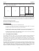
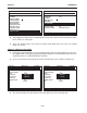
The first step is to enable the DC current input port.
From Analog Input setup:
To access the [Iin] option list press the <Right Arrow> twice.
To move the cursor down to [Aux (n)] press the <Down Arrow> and then <ENT>. This enables
the port to receive an input current. The cursor moves to [4 mA].
To enable numeric entry press the <Right Arrow>. Type a numeric value corresponding to a 4
mA input signal. To store the data press <ENT>. This moves the cursor to [20 mA].
To enable the numeric entry press the <Right Arrow>. Type the numeric value corresponding to
a 20 mA input signal. To store the data, press <ENT>.
2.11 THE DIAGNOSTICS DATA MENU
Some Diagnostic Data items require a successful transducer installation and meter initialization to
become available. These will report [Chan Not Setup] until you complete the installation procedure.
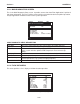
The Diagnostics Data menu provides real-time application and setup data, plus test routines for the
selected channel. To receive the best technical support, please be prepared to report any diagnostic
data item upon request. Note also that these menus contain information that may only be meaningful to
our technical support staff.
The available diagnostic data depends on the meter type and channel configuration. All diagnostics are
available when you select channel 1 or 2 in [Dual Channel Flow], [Ch 1+2 Flow] or [Ch 1-2 Flow]
modes. In [Dual Beam Flow] mode, all diagnostic items are available for [Path 1] or [Path 2]. Some
items are not available (N/A) when you select virtual channel [1 and 2]. In addition, selecting virtual
Channel 3, in either the [1+2 Flow] or [1-2 Flow] modes will limit the list to flow data only.
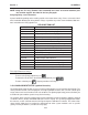
Note that the flowmeter recognizes the first analog input variable that is assigned to any given param-
eter and ignores any subsequent input with the same assignment. For example, if Iin1 and Iin2 are both
assigned to represent Temperature (Deg F), the meter will only use the temperature input from Iin1.
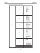
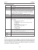
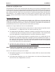
I/O Data Control Analog Inp Setup Iin1 Input Off
Aux
S.G.
cS
cP
PSIA
BARA
Deg F
Deg C
4 mA numeric entry
20 mA numeric entry
Iin2/Iin3/Iin4 See Iin1 option list
NOTE: Refer to the Installation Drawings or I/O Module markings for the locations of these
inputs and wiring procedures.