1.90 11 Alarms 11.1 General 11 Alarms 11.1 General The control contains permanently active monitors which detect malfunctions in the NC, interface controller and machine at such an early stage that damage to the workpiece, tool or machine is largely ruled out. In the event of malfunctions, machining is first interrupted and the drives shut down, the cause of the fault being stored and displayed as an alarm. At the same time the PLC is informed that an NC alarm is present.
11 Alarms 11.2 Display of all messages and alarms with DIAGNOSIS softkey 11.2 11.90 Display of all messages and alarms with DIAGNOSIS softkey If the monitor responds, this may be due to a number of different malfunctions simultaneously. However, only the least significant alarm number is displayed in the alarm line.
11.90 11 Alarms 11.3 Alarm numbers and alarm groups / Clearing alarms Tabular overview with assignment of alarm number and clear mode: Alarm number 1 .... 40 .... 15 99 16 ... 39 Alarm group POWER ON alarms V.24 (RS 232) alarms Alarm cleared only by ... Switching on the control 1. Calling softkey menu containing the ”DATA IN-OUT” function 1) 2. Actuating the ”DATA IN-OUT” softkey 3. Actuating the ”STOP” softkey 100* .... 196* RESET alarms/ axis-specific (*=axis no.
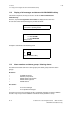
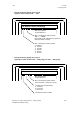
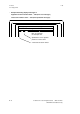
11 Alarms 11.4 Alarm display on screen 11.4 11.90 Alarm display on screen Messages from the monitor are displayed on the screen in the ”Alarm line”. The ”Alarm line” is the second line on the screen from the top. ALARM LINE Area for alarm number and additional designations 11.5 Area for alarm text Display format There are 4 types of display format: • Example illustrating display format type A Applicable to alarm numbers 0 .... 39 and 2000 ...... 2999 2152 ORD 2 Spindle speed too high Max.
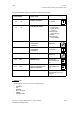
11.90 • 11 Alarms 11.5 Display format Example illustrating display format type B Applies to alarm numbers 1000 ...... 1963 116* ORD12 Contour monitoring Max. 28 characters for descriptive text Max. 5 characters for ordinal number ORD 1 ..... ORD99 (the ordinal number indicates the sequence in which the alarms occurred) Max.
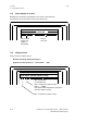
11 Alarms 11.5 Display format • 11.90 Example illustrating display format type D Applicable to alarm numbers 6000 .... 6163 (PLC error messages) and to alarm numbers 7000 .... 7063 (PLC operational messages) 6148 PLC Overtemperature in EU Max.
01.93 11.6 11 Alarms 11.6 Alarm list POWER ON Alarm list POWER ON 1 Cause: Scan: Explanation: Remedy: Battery alarm - power supply Voltage of back-up battery • With POWER ON • Cyclically Replace battery (see Instruction Manual) The battery voltage has dropped to such a level that buffering of the user memories is only guaranteed for a short period. Replace battery (see Instruction Manual).
11 Alarms 11.6 Alarm list POWER ON 5 Scan: Explanation: Remedy: 7 Too many inp. buffer param. When formatting user program memory with ”FORMAT USER M. ” softkey. The input buffer parameters (MIB parameters) require so much space in the user memory that the user program memory is now less than 13 Kbytes. Correct MD 5 (enter lower value) and reformat user program memory. EPROM error Scan: Effect: • • • • • Explanation: • Remedy: • 8 Scan: Effect: Explanation: Remedy: 11–8 09.
09.91 11 Alarms 11.6 Alarm list POWER ON 9 Scan: Effect: Explanation: 10 Scan: Effect: Explanation: Remedy: 11 Scan: Effect: Explanation: Remedy: 12 Scan: Effect: Remedy: © Siemens AG Memory too small for UMS With POWER ON UMS declared invalid On switching on, the contents of the UMS are checked and an address list then prepared. This address list requires a certain amount of storage space in the RAM area. UMS lists are too large.
11 Alarms 11.6 Alarm list POWER ON 13 Scan: Effect: Remedy: RAM error on CPU • • • • 14 Scan: Effect: Remedy: With POWER ON Error in RAM area of module Format user memory and clear part program in installation overall reset mode Replace module RAM error on memory module • • • • 11–10 11.
09.91 11 Alarms 11.7 RS232C (V.24) Alarms 11.7 RS232C (V.24) Alarms 16 Effect: Explanation: Remedy: 17 Effect: Explanation: Remedy: 18 Effect: Explanation: Remedy: © Siemens AG Parity error RS232C (V.24) • RS232C (V.24) transmission interrupted • Last block declared invalid The alarm can only be activated when the setting data ”with parity bit” is set. The parity of the started character (8 data and 1 parity) is incorrect. The alarm has no connection with the RS232C (V.
11 Alarms 11.7 RS232C (V.24) Alarms 19 Effect: Explanation: Remedy: 20 Effect: Explanation: Remedy: 22 Explanation: Remedy: 11–12 09.91 I/O device not ready RS232C (V.24) • • • • No files are read in Low-level DSR signal from external device Activate external device Do not use DSR PLC-alarm-mem. not formated • No PLC alarm texts read in The memory for PLC alarm texts was not set up properly (formatted). Sequence: a. Set NC MD 5012 bit 7 b. Key + NC ON c. d. e. f.
09.91 11 Alarms 11.7 RS232C (V.24) Alarms 23 Cause: Effect: Explanation: Remedy: 24 Effect: Explanation: Remedy: 26 Cause: Effects: Remedy: © Siemens AG Char. parity error RS232C (V.24) Tape dirty or damaged • RS232C (V.24) transmission interrupted • Last block declared invalid Depending on the definition of program start ”%” or ”EOB”, the NC automatically specifies ISO or EIA code and thus character parity after this character has been received.
11 Alarms 11.7 RS232C (V.24) Alarms 27 Cause: 09.91 Data input disabled RS232C (V.24) Effect: One of the following was read in in normal mode: • NC/PLC-MD without active password • PLC program (PCP), PLC alarm texts (only possible in overall reset mode) In overall reset mode PLC alarm texts were read in and NC MD 5012.7=0. No data stored. Remedy: Correct the conditions. 28 Effect: Explanation: 29 Cause: Effect: Remedy: 30 Cause: Effects: Remedy: 11–14 Circ. buffer overflow RS232C (V.
09.91 11 Alarms 11.7 RS232C (V.24) Alarms 31 Cause: Remedy: 32 Cause: Effect: Remedy: 33 Cause: Effect: Remedy: Explanation: © Siemens AG No free PP number RS232C (V.24) The maximum number of programs specified by means of machine data has been reached. • Erase old programs and reorganize memory • Modify MD 8 and reformat part program memory Sequence: a. ”SET UP OVERALL RESET” mode b. ”FORMAT USER MEM.” softkey c. ”CLEAR PARTPR.” softkey Old programs are then deleted!! Data format error RS232C (V.
11 Alarms 11.7 RS232C (V.24) Alarms 34 Cause: Effect: Remedy: 35 Cause: Scan: Effect: Remedy: 36 Cause: Remedy: 11–16 09.91 Operator error RS232C (V.24) Data transmission initiated at the NC and the PLC issues a second start signal No data read in Stop data input and restart Reader error RS232C (V.
01.93 11 Alarms 11.7 RS 232 C (V.24) Alarms POWER ON alarms 40 Cause: Effect: Remedy: 41 Cause: Explanation: 48 Scan: Effect: Explanation: Remedy: 87 Cause: Effect: Comment: © Siemens AG Wrong data in MD 576* Wrong data in MD 576* bit 7, 6, 5 NC START disabled Activate option or check MD 576* Error absolute submodule Error when using a SIPOS absolute submodule The type of error can be seen from the line ”Status absolute submodule” in the ”Service data axis” display. The error number is displayed.
11 Alarms 11.8 Axis-specific RESET alarms 11.8 09.91 Axis-specific RESET alarms 104* DAC limit reached Scan: Effect: Explanation: Cyclically No direct effect. The error enters the following error Alarm 156* Setpoint at DAC is higher than input in MD 268* (max. DAC setpoint).
09.91 11 Alarms 11.
11 Alarms 11.8 Axis-specific RESET alarms 132* Scan: Effect: Explanation: Remedy: 136* Scan: Effect: Explanation: Remedy: 148* 152* Scan: Effect: Explanation: Remedy: 11–20 09.
09.91 11 Alarms 11.
11 Alarms 11.8 Axis-specific RESET alarms 172* 176* Scan: Effect: Explanation: Remedy: Note: 180* Cause: Effect: Remedy: 184* Scan: Effect: Explanation: Remedy: 196* Explanation: 11–22 01.93 + Working area limit - Working area limit During processing in automatic mode During axis traversing in JOG, INC and REPOS mode • NC START disabled • Setpoint 0 Working area limitation in the setting data has been reached.
09.91 11 Alarms 11.9 General RESET alarms 11.9 General RESET alarms 2000 Scan: Effect: Significance: Remedy: Caution: 2030 Cause: Emergency stop Cyclically • NC START disabled • Setpoint 0 • Servo enable cancelled after time in MD 156 has expired • Follow-up mode PLC outputs ”EMERGENCY STOP” signal to NC. • Check with PLC-STATUS whether Q 78.
11 Alarms 11.9 General RESET alarms 2034 Explanation: Remedy: 2035 Cause: Effect: Explanation: 2036 Scan: Significance: 09.91 Speed reduction area The software pre-limit switch has been overrun and the axes braked to reduction speed.
09.91 11 Alarms 11.9 General RESET alarms 2037 Explanation: 2038 Explanation: Effect: Remedy: 2039 Scan: Effect: Significance: Remedy: 2040 Effect: Explanation: 2041 Effect: Explanation: Remedy: © Siemens AG Prog. S value too high Programmed, overstored spindle speed ”S” exceeds ”16 000”. Enter slower spindle speed (S value limited in control to ”16 000”). Path feed too great • The value entered in the machine data ”Max. velocity” exceeds the permitted value range.
11 Alarms 11.
09.91 11 Alarms 11.9 General RESET alarms 2048 Effect: Remedy: 2056 Circle end point error • • • NC START disabled Programmed circle end point not on circle End point is further away by more than the input limit in MD • No geometry in first block of contour subroutine with L95 stock removal cycle Correct program Travel thru transf. center Explanation: • Remedy: • • 2057 Opt. thread/rev.
11 Alarms 11.9 General RESET alarms 2059 Explanation: 2060 Significance: 2061 Effect: Remedy: 2062 Cause: Remedy: 2063 Effect: Explanation: Remedy: 11–28 09.91 G92 Program error • Use of an illegal address character G92 is only allowed with address ”S” (programmed spindle speed limitation for G96) or ”P” (cylindrical interpolation).
11.90 11 Alarms 11.9 General RESET alarms 2064 Scan: Explanation: Effect: Remedy: Note: 2065 Scan: Effect: Explanation: Remedy: 2066 Scan: Effect: Explanation: Remedy: 2067 Scan: Effect: Explanation: Remedy: © Siemens AG Program error round axis During processing in automatic/MDI mode In the case of rounding to half or full degrees with a rotary axis, the control monitors the programmed positions to ensure that rounding has been correctly performed.
11 Alarms 11.9 General RESET alarms 2068 Scan: Effect: Explanation: Remedy: 2072 Explanation: 2073 Explanation: 2074 Explanation: 2075 Explanation: 11–30 11.90 Pos. behind working area During processing in AUTOMATIC/MDI • NC START disabled • Programmed travel not processed Programmed end position of block is behind working area limitation in one or more axes.
11.90 11 Alarms 11.9 General RESET alarms 2076 Explanation: 2077 Explanation: Incorrect G02/G03 (contour definition) Circle direction not possible with defined contour Incorrect block sequence (contour definition) Several blocks are required for calculating contour definition: • Block sequence incorrect • Data not sufficient (under-determined) Example: N10...B15 LF N20...
11 Alarms 11.9 General RESET alarms 2087 11.90 Coord. rotation n. allowed Explanation: When coordinate rotation has been programmed in the NC program a circular motion is to be performed immediately after changing the overall rotating angle. Remedy: Check NC program 2088 Cause: Remedy: 2089 Cause: Remedy: 2152 Battery alarm abs. submod. 1 Battery voltage too low Battery test every 10 minutes Replace battery submodule on absolute submodule 1 with control under power. Battery alarm abs. submod.
11.90 11 Alarms 11.
11 Alarms 11.9 General RESET alarms 2161 Effect: Significance: Remedy: 2171 Explanation: Remedy: 2172 Explanation: Remedy: 2173 Explanation: Remedy: 2183 Explanation: 11–34 01.93 Scale change not allowed Machining halted Scale change not allowed in NC program Check NC program with G51 X.. Y.. Z.. U.. P Approach not possible The control supplements no more than one axis in the programmed plane. Approach is not possible when two axes in the programmed plane are to be supplemented.
01.93 11 Alarms 11.9 General RESET alarms 2184 Explanation: 2189 Explanation: 2190 Explanation: 2191 Explanation: Remedy: 2192 Cause: Effect: Remedy: © Siemens AG M function for C axis invalid M functions reserved by the NC have been used for selecting/deselecting the rotary axis mode (e.g.
11 Alarms 11.9 General RESET alarms 2193 Cause: Abhilfe: 2194 Cause: Remedy: 11–36 01.93 No additional axes possible This occurs only at NC Start after block search in the target block when the MD ”Add axis after block search” have been set: • axes are to be added in G36 blocks • axes are to be added in G98 blocks without axis traverse motion. Do not perform block search on this block.
09.91 11 Alarms 11.10 RESET alarms spindle-specific 11.10 RESET alarms spindle-specific 225* Scan: Explanation: Remedy: 226* Scan: Effect: Explanation: Remedy: 227* Remedy: Effect: Explanation: Remedy: 228* Scan: Effect: Remedy: © Siemens AG Spindle speed too high Only when NC MD 520* bit 2 is set (encoder available) The actual spindle speed is greater than that set in the machine data or in the setting data. • Program smaller S value • NC MD 403* to 410* (max.
11 Alarms 11.11 Alarm list ACKNOWLEDGE 09.91 11.11 Alarm list ACKNOWLEDGE 3000 Explanation: Remedy: 3001 Explanation: Remedy: 3002 Explanation: Remedy: 3003 Explanation: Remedy: 11–38 General program error A general programming error which cannot be precisely defined has been made in a block in the program. Example: • The programmed axis is not available at the machine. • Incorrect interpolation parameters programmed. • Axis duplication option active and D number in part program greater than 49.
09.91 11 Alarms 11.11 Alarm list ACKNOWLEDGE 3004 Explanation: Remedy: CL800 error • • • • • • • • • • • • • • • • 3005 Explanation: Remedy: 3006 Explanation: @ function not available Incorrect address after @ Number of addresses after @ incorrect Value in K, R or P not permissible Number of decades excessive No decimal point allowed Jump address incorrectly defined System memory (NC MD, PLC MD, TO, ...
11 Alarms 11.11 Alarm list ACKNOWLEDGE 3007 Explanation: Remedy: 3008 Explanation: Remedy: 3009 Explanation: 3010 Significance: Remedy: 11–40 09.
11.90 11 Alarms 11.11 Alarm list ACKNOWLEDGE 3011 Explanation: Remedy: 3012 Explanation: Remedy: 3013 Explanation: Remedy: 3016 Effect: Explanation: Remedy: © Siemens AG Number of axes > 2 / axes twice An axis has been programmed twice in the same block. More axes have been programmed than are available at the machine As for Alarm 3000 • • Block not in memory Program not terminated with M02 / M30 / M17.
11 Alarms 11.11 Alarm list ACKNOWLEDGE 3017 Scan: Effect: Explanation: Remedy: 3018 Scan: Effect: Explanation: Remedy: 3019 Explanation: Remedy: 3020 11.90 Part program no.
11.90 11 Alarms 11.11 Alarm list ACKNOWLEDGE 3024 Explanation: Remedy: 3025 Display description not available A configured softkey has been used to skip to a display which is not available in the user memory submodule or system memory. • Check display number • Check softkey function Display description error Explanation: • Remedy: • • • • 3026 Explanation: Remedy: Graphics / text too volum.
11 Alarms 11.11 Alarm list ACKNOWLEDGE 3028 Too many fields / variables Explanation: • Remedy: • • • 3029 Explanation: Remedy: 3030 Explanation: Remedy: Note: 3032 Note: 3033 Explanation: Remedy: 11–44 09.91 Configuring error in selected display. The number of fields or variables is limited in view of the specific length of the transfer buffer. A maximum number of fields/variables cannot be stated since the fields/variables can have different formats and positions.
11.90 11 Alarms 11.11 Alarm list ACKNOWLEDGE 3034 Explanation: Remedy: 3040 Explanation: Remedy: Note: 3041 Explanation: 3042 Explanation: Remedy: 3043 Explanation: Remedy: © Siemens AG Text not available The followings texts have been incorrectly linked or not linked at all in the selected display: • Menu texts • Dialog texts • Mode texts • Alarm texts etc. Check display using programming workstation Fields / var.
11 Alarms 11.11 Alarm list ACKNOWLEDGE 3046 Explanation: Remedy: 3048 11.90 Variable error A variable has been selected which cannot be represented in control. Check display using programming workstation; re-input variable if necessary Wrong workpiece definition Explanation: Minimum and maximum values have been reversed when defining the workpiece. Example: Xmin. = 100 Xmax. = 50 Remedy: Check workpiece definition for valid values.
01.93 11 Alarms 11.11 Alarm list ACKNOWLEDGE 3081 Explanation: Remedy: 3082 Explanation: Remedy: 3083 Explanation: Remedy: 3084 Explanation: Remedy: 3087 Erläuterung: © Siemens AG CRC not selected on approach The function ”soft contour approach and retract” is only possible when cutter radius compensation has been selected. G41/ G42 D0 is then considered to have been selected. Select CRC Feed missing/not prog.
11 Alarms 11.11 Alarm list ACKNOWLEDGE 3200 Explanation: 3201 01.93 e.g. 1N5 illegal working area limitation N5 = axis number 5 (a number from 1 to 7 is possible) 1 =min. working area limitation 2=max. working area limitation This alarm is issued when the entry for working area limitation is beyond the permitted values. Together with this alarm, the values are limited to the maximum possible. This alarm sinply indicates that this limitation has taken place.
11.90 11 Alarms 11.11 Alarm list ACKNOWLEDGE 6000 : 6063 Explanation: Remedy: 6100 Cause: Effect: Remedy: 6101 Cause: Effect: Remedy: 6102 Cause: Effect: Remedy: © Siemens AG PLC user alarm Initiation bit was set in the PLC user program Check PLC program or machine function Signal converter missing Load or transfer command to unavailable peripheral device (I/Os), e.g.
11 Alarms 11.11 Alarm list ACKNOWLEDGE 6103 Cause: Effect: Remedy: 6104 Cause: Effect: Remedy: 6105 Cause: Effect: Explanation: Remedy: 6106 Cause: Effect: Remedy: 6107 Cause: Effect: Explanation: Remedy: 11–50 09.91 Transfer to missing DB L DW or T DW without prior ”opening” (A DB ...) of a data block PLC STOP Check PLC program Substitution error Parameterization error in BMW or BDW command PLC STOP Correct PLC program Missing MC 5 block Unavailable block in control called (OB, PB, SB, FB).
11.90 11 Alarms 11.11 Alarm list ACKNOWLEDGE 6108 Cause: Effect: Explanation: Remedy: 6109 Cause: Effect: Explanation: Remedy: 6110 Cause: Effect: Explanation: Remedy: 6111 Cause: Effect: Explanation: © Siemens AG Illegal segment block transfer TNB / TNW Source : Segment No. 0-A allowed Destination : Segment No.
11 Alarms 11.11 Alarm list ACKNOWLEDGE 6112 Cause: Effect: Explanation: 6113 Cause: Effect: Remedy: 6114 Cause: Effect: Remedy: 6115 Cause: Effect: Remedy: 6116 Cause: Effect: Remedy: 11–52 11.90 MC 5 - command STP STP instruction programmed PLC STOP PLC STOP after termination of STEP 5 program processing Illegal MC 5 timer / counter STEP 5 timer or counter not available or not enabled via MD. Time with a constant of 10 ms progr. PLC STOP.
11.90 6117 Cause: Effect: Remedy: 6118 Cause: Effect: Remedy: 6119 Cause: Effect: Remedy: 6121 Cause: Effect: Remedy: 6122 Cause: Remedy: © Siemens AG 11 Alarms 11.11 Alarm list ACKNOWLEDGE MD 0001: CPU load PLC MD 1 greater than 20 % PLC STOP Correct MD MD 0003: Alarm runtime PLC MD 3 greater than 2500 µs PLC STOP Correct MD MD 0005: Cycle time PLC MD 5 greater than 320 ms PLC STOP Correct MD MD 0006: Last MC 5 time PLC MD 6 greater than 31 PLC STOP Correct MD This arrangement n.
11 Alarms 11.11 Alarm list ACKNOWLEDGE 6123 Cause: Effect: Remedy: 6124 Cause: Effect: Remedy: 6125 Cause: Effect: Remedy: Explanation: 6126 Cause: Effect: Remedy: Explanation: 6127 Cause: Effect: Remedy: 11–54 09.
09.91 11 Alarms 11.11 Alarm list ACKNOWLEDGE 6128 Cause: Effect: Remedy: 6130 Wrong I/O jumpering Same address for central and distributed I/O device PLC STOP Change address decoding Synch. error basic program Cause: Synchronization pattern for assembler function blocks no longer correct Effect: Remedy: PLC STOP PLC OVERALL RESET, reload PLC program if necessary 6131 Synch.
11 Alarms 11.11 Alarm list ACKNOWLEDGE 6134 Effect: Remedy: 6135 Effect: Remedy: 6136 Effect: Remedy: 6137 Effect: Remedy: 6138 Cause: Effect: Explanation: Remedy: 11–56 11.
09.91 11 Alarms 11.11 Alarm list ACKNOWLEDGE 6139 Cause: Effect: Remedy: 6140 Cause: Effect: Remedy: 6143 Cause: Effect: Remedy: 6144 Cause: Effect: Remedy: 6145 Cause: Effect: Remedy: 11–57 EU transmission error Incorrect protocol between EU and central controller (NC).
11 Alarms 11.11 Alarm list ACKNOWLEDGE 6146 Cause: Effect: Remedy: 6147 Cause: Effect: Explanation: 6148 Cause: Effect: Explanation: Remedy: 6149 Cause: Effect: Remedy: 11–58 11.
11.90 11 Alarms 11.11 Alarm list ACKNOWLEDGE 6150 Cause: Effect: Remedy: 6151 Cause: Effect: Remedy: 6152 Cause: Effect: Explanation: Remedy: 6153 Cause: Effect: Explanation: Remedy: © Siemens AG Timeout: MC5 user PLC STOP (S5 prog.
11 Alarms 11.11 Alarm list ACKNOWLEDGE 6154 Cause: Effect: Remedy: 6155 Effect: Remedy: 6156 Cause: Effect: Remedy: 6157 Cause: Effect: Remedy: 11–60 Timeout: 11.
11.90 11 Alarms 11.11 Alarm list ACKNOWLEDGE 6158 Cause: Effect: Explanation: Remedy: 6159 Cause: Effect: Explanation: Remedy: 6160 Cause: Effect: Explanation: Remedy: 6161 Cause: Effect: Remedy: © Siemens AG Timeout with I / O transfer Central I/O device no longer signalling PLC STOP All I/O modules detected on start-up (If the no.
11 Alarms 11.11 Alarm list ACKNOWLEDGE 6162 Cause: Effect: Explanation: Remedy: 6163 11.90 Processing time delay OB2 The alarm program interrupted itself. PLC STOP, dependent on PLC MD 2003 Bit 0. Evaluate diagnostic DB. Time-optimize OB2, i.e.