User Manual Flying Saw SIMOTION Flying Saw V1.
General Notes A4027118-A0414 Copyright © Siemens AG 2008 All rights reserved Manual_SIMOTION Flying Saw_V1.4.doc SIMOTION Flying Saw We reserve the right to make technical changes to this product. Copyright Reproduction, transmission or use of this document or its contents is not permitted without express written authority. Offenders will be liable for damages. All rights, including rights created by patent grant or registration or a utility model or design, are reserved. V 1.
General Notes SIMOTION Flying Saw A4027118-A0414 General Notes Copyright © Siemens AG 2008 All rights reserved Manual_SIMOTION Flying Saw_V1.4.doc Note The standard applications are not binding and do not claim to be complete regarding the circuits shown, equipping and any eventuality. The standard applications do not represent customer-specific solutions. They are only intended to pro-vide support for typical applications.
General Notes SIMOTION Flying Saw A4027118-A0414 Qualified personnel In the sense of this documentation qualified personnel are those who are knowledgeable and qualified to mount/install, commission, operate and service/maintain the products which are to be used. He or she must have the appropriate qualifications to carry-out these activities e.g.: • Trained and authorized to energize and de-energize, ground and tag circuits and equipment according to applicable safety standards.
Foreword SIMOTION Flying Saw A4027118-A0414 Foreword Standard SIMOTION application A standard SIMOTION application comprises the following components: One or several software objects or code blocks with defined interfaces that can be simply integrated into other software projects – without requiring any significant programming – in order to fulfill a precisely defined technology task there.
Foreword SIMOTION Flying Saw A4027118-A0414 Document structure The documentation of this application is sub-divided into the following main section: Copyright © Siemens AG 2008 All rights reserved Manual_SIMOTION Flying Saw_V1.4.doc Section V 1.4 Description A Section A will provide you with everything that you require to obtain an overview of this standard application. This Section explains the prerequisites and the objective when using this application.
List of contents SIMOTION Flying Saw A4027118-A0414 List of contents Copyright © Siemens AG 2008 All rights reserved Manual_SIMOTION Flying Saw_V1.4.doc Section A: Prerequisites and objectives .................................................................. 10 1 1.1 1.1.1 1.1.2 1.1.3 1.2 1.2.1 1.2.2 1.2.3 1.3 Basic information ......................................................................................... 11 Prerequisites.....................................................................
List of contents SIMOTION Flying Saw 5.1 5.1.1 5.1.2 5.2 5.2.1 5.2.2 5.2.3 5.2.4 5.2.5 5.2.6 5.2.7 A4027118-A0414 Brief instructions to demonstrate .................................................................... 41 Structure overview .......................................................................................... 42 Brief instructions ............................................................................................. 43 Detailed operating instructions ...........................
List of contents SIMOTION Flying Saw 8.4 8.5 8.6 A4027118-A0414 Using the restart bit......................................................................................... 83 Error messages .............................................................................................. 83 Help functions within the core “flying saw” functions ...................................... 85 Copyright © Siemens AG 2008 All rights reserved Manual_SIMOTION Flying Saw_V1.4.doc Section D: Program description.....
Section A: Prerequisites and objectives Basic information Flying Saw with SIMOTION A4027118-A0414 Section A: Prerequisites and objectives Content Section A will provide you with everything that you require to obtain an overview of this standard application. The prerequisites and the objective for using this standard application are presented. The applications shown will give you a good understanding for what this standard application can be used for.
Section A: Prerequisites and objectives Basic information Flying Saw with SIMOTION A4027118-A0414 1 Basic information 1.1 Prerequisites 1.1.1 Target group The standard application is conceived for all programmers and users who wish to quickly and simply implement a flying saw using SIMOTION. 1.1.2 Knowledge base In order to use this technology template, you should be able to use SCOUT and technology objects and technology function calls in SIMOTION.
Section A: Prerequisites and objectives Basic information Flying Saw with SIMOTION A4027118-A0414 Principle design of a "flying saw" The material is fed-in as an endless web (e.g. plastic, sheet steel or fiber board) using a conveyor belt that runs with a constant velocity. The position of the cut on the material web is either sensed using a print mark using a sensor or is specified by the control after a cut length has been passed that can be adjusted. The synchronous position is simultaneously defined.
Section A: Prerequisites and objectives Basic information Flying Saw with SIMOTION A4027118-A0414 The user program only has to control the material feed and to supply the core function with the correct parameters. Additional function of the standard application Further, using this standard application, after the material has been cut with the cutting device, a gap can be created between the individual cut pieces.
Section A: Prerequisites and objectives Basic information Flying Saw with SIMOTION A4027118-A0414 The program fulfills the following tasks: • Operating mode manager for the complete (demonstration) machine • The control of the (demonstration) machine • The core functions of the "flying saw" functionality with absolute gearing • All of the machine functions that are relevant for the demonstration case environment are simulated • The (demonstration) machine is displayed on the WinCCflex screen Thi
Section A: Prerequisites and objectives Uses Flying Saw with SIMOTION A4027118-A0414 2 Uses 2.1 Applications 2.1.1 Controls that are permitted The standard “flying saw” application has only been tested for use in the following control system: • SIMOTION D 435 However, it can also be used – without any significant additional costs – also in the SIMOTION P or SIMOTION C controls. Copyright © Siemens AG 2008 All rights reserved Manual_SIMOTION Flying Saw_V1.4.doc 2.1.
Section A: Prerequisites and objectives Uses Flying Saw with SIMOTION 2.1.3 A4027118-A0414 Properties and features of the core “flying saw” functions Copyright © Siemens AG 2008 All rights reserved Manual_SIMOTION Flying Saw_V1.4.doc The following properties and features were taken into account when implementing the core functions, and can also be used in a user program that you generate yourself: V 1.
Section A: Prerequisites and objectives Uses Flying Saw with SIMOTION 2.2 A4027118-A0414 Application environment The standard “flying saw” application can be used in the following hardware environment: Fig. 2-1 Application environment of the standard “flying saw” application PG / PC SIMOTION D Copyright © Siemens AG 2008 All rights reserved Manual_SIMOTION Flying Saw_V1.4.
Section A: Prerequisites and objectives Structure and function Flying Saw with SIMOTION A4027118-A0414 3 Structure and function 3.1 Design of the "flying saw" 3.1.1 General design The "flying saw", which is based on the "flying saw" core function comprises a spindle axis that is mounted on the cutting unit. 3.1.
Section A: Prerequisites and objectives Structure and function Flying Saw with SIMOTION A4027118-A0414 Table 3-1: Explanation of the parameterizable physical quantities Copyright © Siemens AG 2008 All rights reserved Manual_SIMOTION Flying Saw_V1.4.
Section A: Prerequisites and objectives Structure and function Flying Saw with SIMOTION 3.2 A4027118-A0414 Operating states of the "FlyingSaw-FB" The “FlyingSaw FB” automatically controls the “flying saw” axis to implement the required level of functionality. This functionality is sub-divided into five operating states so that the sequences at the “flying saw” are implemented as a result of the states or also as a result of the transitions between the states.
Section A: Prerequisites and objectives Structure and function Flying Saw with SIMOTION A4027118-A0414 starting position and is ready to synchronize to the material web. The flying saw axis waits in the “enable” state. • Automatic (3) The flying saw axis has been synchronized to the material web and cuts the material as specified. • Manual (4) The flying saw axis is in the manual mode and the user can manually move the shaft. The flying saw axis waits in the “enable” state.
Section B: The application example as demonstration system St t df ti Flying Saw with SIMOTION A4027118-A0414 Section B: The application example as demonstration system Contents All of the necessary steps to commission the standard “flying saw” application as demonstration system are explained in Section B. Preparations and parameterizing operations are also explained. Further, you are told how you can use the WinCCflex Pro man-machine interface (screen) of the application example step-by-step.
Section B: The application example as demonstration system I t lli th h d d ft Flying Saw with SIMOTION A4027118-A0414 4 Installing the hardware and software 4.1 Regarding your safety 4.1.1 Safety information and instructions Pictograms, signal words and text Every piece of safety information/instruction in this document is designated by text graphics – comprising pictogram and signal word, and supplemented by explanatory text.
Section B: The application example as demonstration system I t lli th h d d ft Flying Saw with SIMOTION 4.1.2 A4027118-A0414 Responsibilities of the operator Correct use The correct use of the application components exclusively relates to the open-loop and closed-loop control of test set-ups that were adapted to the power/performance of the application components.
Section B: The application example as demonstration system I t lli th h d d ft Flying Saw with SIMOTION A4027118-A0414 Qualification of personnel The operating company/person may only deploy trained, authorized and reliable personnel. In so doing, all safety regulations must be carefully observed. Personnel must receive special instructions regarding the hazards/dangers that can occur. 4.
Section B: The application example as demonstration system I t lli th h d d ft Flying Saw with SIMOTION A4027118-A0414 Table 4-1 Hardware components Hardware element Diagram Order No./MLFB and functions Training case, SIMOTION D435 with SINAMICS S120 Copyright © Siemens AG 2008 All rights reserved Manual_SIMOTION Flying Saw_V1.4.
Section B: The application example as demonstration system I t lli th h d d ft Flying Saw with SIMOTION A4027118-A0414 Table 4-2 Hardware configuration and mounting No. Action Comment 1 Connect the MPI/DP interface of your PG/PC to the righthand MPI/DP interface (contact X136) of the SIMOTION D435 using a PROFIBUS cable and switch the terminating resistors in the two terminating connectors of the cable to “On”.
Section B: The application example as demonstration system I t lli th h d d ft Flying Saw with SIMOTION 4.3 A4027118-A0414 Installing the standard SIEMENS software Minimum required releases Table 4-3 Versions Component Version. STEP 7 V5.4 + SP2 SIMOTON SCOUT V4.1.1.6 WinCCflex Advanced 2007 Hotfix 4 Installation Copyright © Siemens AG 2008 All rights reserved Manual_SIMOTION Flying Saw_V1.4.doc Please install the following • Step 7 V5.4 incl. SP2 • SIMOTION SCOUT V4.1.1.
Section B: The application example as demonstration system I t lli th h d d ft Flying Saw with SIMOTION A4027118-A0414 • When RDY lights green and STOP lights orange, set the SIMOTION D435 mode switch to the 0 position (RUN) • RDY and RUN are green Once the factory setting has been restored, the SIMOTION D435 has PROFIBUS address 2 and the baud rate is 1.5 Mbit/s. Copyright © Siemens AG 2008 All rights reserved Manual_SIMOTION Flying Saw_V1.4.doc Fig. 4-2 Mode selector switch, SIMOTION D435 V 1.
Section B: The application example as demonstration system I t lli th h d d ft Flying Saw with SIMOTION 4.4.3 A4027118-A0414 Re-configuring the double-axis motor module from 3A/3A to 5A/5A Copyright © Siemens AG 2008 All rights reserved Manual_SIMOTION Flying Saw_V1.4.doc This application example is configured as standard using a 3A/3A motor module. However, there are demonstration cases in the field, which are still equipped with a 5A/5A motor module.
Section B: The application example as demonstration system I t lli th h d d ft Flying Saw with SIMOTION A4027118-A0414 Copyright © Siemens AG 2008 All rights reserved Manual_SIMOTION Flying Saw_V1.4.doc Fig. 4-3: Re-configuring the motor module V 1.
Section B: The application example as demonstration system I t lli th h d d ft Flying Saw with SIMOTION 4.4.4 A4027118-A0414 Setting the Ethernet interface of the PG/PC Setting the PG/PC interface Table 3-5: Setting the PG/PC interface No. Action Comment 1 In SIMOTION SCOUT open the interface configuration using OPTIONS Æ SET PG/PC INTERFACE... Copyright © Siemens AG 2008 All rights reserved Manual_SIMOTION Flying Saw_V1.4.
Section B: The application example as demonstration system I t lli th h d d ft Flying Saw with SIMOTION A4027118-A0414 Copyright © Siemens AG 2008 All rights reserved Manual_SIMOTION Flying Saw_V1.4.doc 6 Open Properties by double-clicking on the PG/PC(1). 7 Under the “Assignment” tab (this is already automatically selected), the ETHERNET interface used must be listed under “Assigned”. If this is already the case, then select this and set the checkmark for S7ONLINE access active.
Section B: The application example as demonstration system I t lli th h d d ft Flying Saw with SIMOTION A4027118-A0414 9 The interface of the control is now assigned the interface of the PG/PC. Select this and if it has still not been set, then set the checkmark for S7ONLINE access Active. Acknowledge your entry with OK. Copyright © Siemens AG 2008 All rights reserved Manual_SIMOTION Flying Saw_V1.4.doc Under certain circumstances, the Ethernet line of the PG/PC will have a ”yellow border”.
Section B: The application example as demonstration system I t lli th h d d ft Flying Saw with SIMOTION A4027118-A0414 Table 3-6: Ethernet address No. Action Comment Copyright © Siemens AG 2008 All rights reserved Manual_SIMOTION Flying Saw_V1.4.doc 1 Open the window Network and Dial-up Connections of your PG/PC and select the network connection to SIMOTION D435 and open its properties. (righthand mouse click Æ Properties – or select the symbol and then FILE Æ PROPERTIES).
Section B: The application example as demonstration system I t lli th h d d ft Flying Saw with SIMOTION A4027118-A0414 3 The Ethernet interface IE2 (X130) of SIMOTION D435 has, as standard, the IP address 169.254.11.22. Copyright © Siemens AG 2008 All rights reserved Manual_SIMOTION Flying Saw_V1.4.doc Select “Use the following IP address” and enter the IP address 169.254.11.23. Enter 255.255.0.0 as “Subnet mask”. 4 The address set above must be identical to the address for the PG/PC.
Section B: The application example as demonstration system I t lli th h d d ft Flying Saw with SIMOTION A4027118-A0414 2 Acknowledge with OK Copyright © Siemens AG 2008 All rights reserved Manual_SIMOTION Flying Saw_V1.4.doc 3 Acknowledge with OK 4 Press No and do not restart 5 Close the hardware configuration and change to Scout V 1.
Section B: The application example as demonstration system I t lli th h d d ft Flying Saw with SIMOTION 4.4.6 A4027118-A0414 Downloading the SIMOTION project of the standard application Table 4-5: Downloading the SIMOTION project No. Action Comment Copyright © Siemens AG 2008 All rights reserved Manual_SIMOTION Flying Saw_V1.4.
Section B: The application example as demonstration system I t lli th h d d ft Flying Saw with SIMOTION A4027118-A0414 6 After starting the download, you will be prompted as to whether you wish to “copy RAM to ROM“ after the download. Always answer this question with Yes as otherwise your program must be again downloaded after power ON/OFF.
Section B: The application example as demonstration system I t lli th h d d ft Flying Saw with SIMOTION A4027118-A0414 12 Now switch the SIMOTION D435 into the RUN state. To do this, click on the SIMOTION-CPU and with the righthand mouse key and target device/operating state, go to the operating state display. 13 Here, click on the RUN button Copyright © Siemens AG 2008 All rights reserved Manual_SIMOTION Flying Saw_V1.4.
Section B: The application example as demonstration system O t t l f th li ti l Flying Saw with SIMOTION 5 A4027118-A0414 Operator control of the application example The application can be used to present SIMOTION D with SINAMICS and get to know and test the functions of the CPU D435. You will find brief instructions on how to demonstrate and present the application in the following Chapter 5.1 Brief instructions to demonstrate.
Section B: The application example as demonstration system O t t l f th li ti l Flying Saw with SIMOTION 5.1.1 A4027118-A0414 Structure overview Please refer to the following diagram for the basic operator control structure with all of the operator areas of the application. The SETTINGS, STATUS and MANUAL displays are not required when presenting the application and are therefore not described in the detailed Operating Instructions. Fig.
Section B: The application example as demonstration system O t t l f th li ti l Flying Saw with SIMOTION 5.1.2 A4027118-A0414 Brief instructions Execute the following steps in the sequence as listed in the following table to demonstrate the application example: Table 5-1: Brief instructions to demonstrate/present the “flying saw” application example No. Action Comment 1 Call the following file "C:\Siemens\Step7\S7Proj\SAP_FlyingSaw\TDOP\ PRO__00.fwd".
Section B: The application example as demonstration system O t t l f th li ti l Flying Saw with SIMOTION A4027118-A0414 6 Once the “flying saw” has reached its starting position, the Flying Saw START button is displayed to activate the “flying saw” Before you activate the “flying saw”, the required cut length should be selected using the Cutlength slider. Copyright © Siemens AG 2008 All rights reserved Manual_SIMOTION Flying Saw_V1.4.
Section B: The application example as demonstration system O t t l f th li ti l Flying Saw with SIMOTION A4027118-A0414 12 After the last cut, the “flying saw” automatically moves to its starting position and waits for new material. Copyright © Siemens AG 2008 All rights reserved Manual_SIMOTION Flying Saw_V1.4.
Section B: The application example as demonstration system O t t l f th li ti l Flying Saw with SIMOTION A4027118-A0414 Material Random print mark offset Start Material Start flying saw Stop Material Copyright © Siemens AG 2008 All rights reserved Manual_SIMOTION Flying Saw_V1.4.
Section B: The application example as demonstration system O t t l f th li ti l Flying Saw with SIMOTION 5.2 A4027118-A0414 Detailed operating instructions A detailed description of the application is provided in these instructions. This is necessary so that you can get to know and test the CPU functions. Prerequisites Copyright © Siemens AG 2008 All rights reserved Manual_SIMOTION Flying Saw_V1.4.doc The following prerequisites must be fulfilled to use the application example: Note V 1.
Section B: The application example as demonstration system O t t l f th li ti l Flying Saw with SIMOTION 5.2.1 A4027118-A0414 Structure overview Please refer to the following diagram for the basic operator control structure with all of the operator areas of the application. Fig. 5-3 Structure overview HOME SETTINGS Copyright © Siemens AG 2008 All rights reserved Manual_SIMOTION Flying Saw_V1.4.doc Manual-Mode MANUAL STATUS Automatic-Mode AUTO 5.2.
Section B: The application example as demonstration system O t t l f th li ti l Flying Saw with SIMOTION A4027118-A0414 The welcome screen is displayed Copyright © Siemens AG 2008 All rights reserved Manual_SIMOTION Flying Saw_V1.4.doc Fig. 5-4 Welcome screen General screen areas The screen forms of the application are handled using buttons at the lower edge of each of the screen forms.
Section B: The application example as demonstration system O t t l f th li ti l Flying Saw with SIMOTION A4027118-A0414 The following functions can be selected using the individual buttons: Table 5-2 General buttons to control/handle the screen forms Button Function You can access the pre-setting screen from every operator screen using the SETTINGS button. You can access the setting-up screen from every operator screen using the MANUAL button.
Section B: The application example as demonstration system O t t l f th li ti l Flying Saw with SIMOTION 5.2.3 A4027118-A0414 Machine parameter settings The standard application allows the following parameters to be adapted: Copyright © Siemens AG 2008 All rights reserved Manual_SIMOTION Flying Saw_V1.4.
Section B: The application example as demonstration system O t t l f th li ti l Flying Saw with SIMOTION A4027118-A0414 Copyright © Siemens AG 2008 All rights reserved Manual_SIMOTION Flying Saw_V1.4.doc Fig. 5-5 SETTINGS operator screen for machine geometry settings V 1.
Section B: The application example as demonstration system O t t l f th li ti l Flying Saw with SIMOTION 5.2.4 A4027118-A0414 Operator control functions in the setting-mode In the manual mode, the material web and flying saw can be manually moved. This standard application does not require any functions that may only be executed in the setting-up mode.
Section B: The application example as demonstration system O t t l f th li ti l Flying Saw with SIMOTION 5.2.5 Note A4027118-A0414 Operator functions of the process in the automatic mode The automatic mode is only available, if • • • There is no fault, Both axes are enabled, and For both of these axes, no manual operator control functions are active. Copyright © Siemens AG 2008 All rights reserved Manual_SIMOTION Flying Saw_V1.4.doc Fig.
Section B: The application example as demonstration system O t t l f th li ti l Flying Saw with SIMOTION A4027118-A0414 Standard operator control Table 5-3: Standard operator control in the automatic mode No. Action Comment 1 Initial situation: The “flying saw” is in the AUTOMATIC-STOPPED mode Copyright © Siemens AG 2008 All rights reserved Manual_SIMOTION Flying Saw_V1.4.
Section B: The application example as demonstration system O t t l f th li ti l Flying Saw with SIMOTION A4027118-A0414 8 Depending on the material velocity and the cutting duration, an actual maximum position of the flying saw is obtained, which is identified by a red bar. 9 You can start to thread the material web or continue motion after the material web was stopped by pressing the Material START button. Copyright © Siemens AG 2008 All rights reserved Manual_SIMOTION Flying Saw_V1.4.
Section B: The application example as demonstration system O t t l f th li ti l Flying Saw with SIMOTION A4027118-A0414 Expanded operator control Table 5-4: Expanded operator control in the automatic mode No. Action Comment Copyright © Siemens AG 2008 All rights reserved Manual_SIMOTION Flying Saw_V1.4.doc 1 If the flying saw is in the AUTOMATIC-STOPPED, operating mode, you can select one of two possibilities: 1. Print Mark Simulation OFF i.e.
Section B: The application example as demonstration system O t t l f th li ti l Flying Saw with SIMOTION A4027118-A0414 6 Here, you can set the velocities for the return to the starting position and also when returning to the starting position in the automatic mode Display areas Fig. 5-8: Flying saw mode Copyright © Siemens AG 2008 All rights reserved Manual_SIMOTION Flying Saw_V1.4.doc This area informs you about the selected and presently active operating mode of the FlyingSaw FB. Fig.
Section B: The application example as demonstration system O t t l f th li ti l Flying Saw with SIMOTION 5.2.6 A4027118-A0414 Technology view The technology view of the application can be selected from every operator screen using the TECHNOLOGY button. Fig. 5-10 Technology view of the flying saw Velocity of the material web Copyright © Siemens AG 2008 All rights reserved Manual_SIMOTION Flying Saw_V1.4.
Section B: The application example as demonstration system O t t l f th li ti l Flying Saw with SIMOTION 5.2.7 A4027118-A0414 Operator control functions in the status display The status display of the application can be selected from every operator screen using the STATUS button. Copyright © Siemens AG 2008 All rights reserved Manual_SIMOTION Flying Saw_V1.4.doc Fig. 5-11: Status You can see the actual state of the FlyingSaw FB in the status display.
Section C: Integrating the core “flying saw” functions Operator control of the application example Flying Saw with SIMOTION A4027118-A0414 Section C: Integrating the core “flying saw” functions Content All of the steps necessary to integrate the core “flying saw” functions into your application are explained in Section C. Preparations and parameterizing operations are also explained. Further, you are also told how to integrate the “FlyingSaw FB” into your application step-by-step.
Section C: Integrating the core “flying saw” functions Program environment and interfaces Flying Saw with SIMOTION A4027118-A0414 6 Program environment and interfaces 6.1.1 Function and identification of the program groups Copyright © Siemens AG 2008 All rights reserved Manual_SIMOTION Flying Saw_V1.4.
Section C: Integrating the core “flying saw” functions Program environment and interfaces Flying Saw with SIMOTION 6.1.2 A4027118-A0414 Program structure All of the functions, implemented in the standard “flying saw” application are listed in the following table according to their assignment to a particular program group and program unit. Table 6-1: Program structure of the standard “flying saw” application Program Section Copyright © Siemens AG 2008 All rights reserved Manual_SIMOTION Flying Saw_V1.
Section C: Integrating the core “flying saw” functions Program environment and interfaces Flying Saw with SIMOTION Program Section Program unit Program module Data unit FS_TEMPL FB_BGD_TEMPLATE_FlyingSaw() FS_PMIPO MT_FS1_PrintmarkDetection() IPO_FS1_IPO_routine() FS_SPB FB_BGD_FS_SPB_in() FB_BGD_FS_SPB_reset() FB_BGD_FS_SPB_read() FB_BGD_FS_SPB_out() SIM SIM_PM IPO_SIM_Printmarks() Startup_SIM() SIM_Var HMI HMI_SAP BGD_HMI_FlyingSaw() Startup_HMI() FB_BGD_HMI_Printmarks() FB_BGD_HMI_Cuts()
Section C: Integrating the core “flying saw” functions Program environment and interfaces Flying Saw with SIMOTION 6.2 A4027118-A0414 Call environment The function block FB_BGD_TEMPLATE_FlyingSaw() of the “flying saw” core function must be cyclically called in the user program. This is the reason that the call can only be made from a program that is incorporated in the background task. Fig.
Section C: Integrating the core “flying saw” functions Program environment and interfaces Flying Saw with SIMOTION A4027118-A0414 • Block interfaces • User interface in the global data area (data unit FS_Var) The function block is signaled changing tasks and modes using the block interface. The function block signals the actual status and possibly occurring faults back to the user program also via this interface.
Section C: Integrating the core “flying saw” functions Program environment and interfaces Flying Saw with SIMOTION Copyright © Siemens AG 2008 All rights reserved Manual_SIMOTION Flying Saw_V1.4.doc Parameter A4027118-A0414 Data type Initial value Description Mode INT 0 Using Mode, the mode is preselected that is activated with the next positive signal edge at the execute input.
Section C: Integrating the core “flying saw” functions Program environment and interfaces Flying Saw with SIMOTION Parameter A4027118-A0414 Data type Initial value Description Input/output parameter (IN/OUT) UsersInterface STRUCT User interface ErrorInterface STRUCT ErrorID of the technology functions InternalData STRUCT Internal data of the sequence control SyncPos Management STRUCT Data of the synchronous position management TimeCalc STRUCT Time calculation data Copyright © Siemens AG 2
Section C: Integrating the core “flying saw” functions Program environment and interfaces Flying Saw with SIMOTION A4027118-A0414 Fig. 6-2 Structure of the global data area of the core “flying saw” function Unit FS_Var User rinterface DW24 TOs used ErrorID of the technology functions DW34 Physical quantities DW58 Internal data of the sequence control Control information DW60 Copyright © Siemens AG 2008 All rights reserved Manual_SIMOTION Flying Saw_V1.4.
Section C: Integrating the core “flying saw” functions Program environment and interfaces Flying Saw with SIMOTION A4027118-A0414 Copyright © Siemens AG 2008 All rights reserved Manual_SIMOTION Flying Saw_V1.4.doc Parameter V 1.4 Data type Initial value Description EndSyncPos [mm] LREAL 20.0 End position of the synchronous range EndPos [mm] LREAL 125.0 Starting position of the cross-cutter ToStartposVelocity [mm/s] LREAL 100.
Section C: Integrating the core “flying saw” functions Program environment and interfaces Flying Saw with SIMOTION A4027118-A0414 Parameter Data type Initial value Description Copyright © Siemens AG 2008 All rights reserved Manual_SIMOTION Flying Saw_V1.4.doc Control information Restart BOOL false If the bit is set (e.g. in the StartUp task), then the template executes a re-initialization and resets the bit.
Section C: Integrating the core “flying saw” functions Integrating the core “flying saw” functions Flying Saw with SIMOTION A4027118-A0414 7 Integrating the core “flying saw” functions 7.1 This is how you integrate core functions into your project Copyright © Siemens AG 2008 All rights reserved Manual_SIMOTION Flying Saw_V1.4.
Section C: Integrating the core “flying saw” functions Integrating the core “flying saw” functions Flying Saw with SIMOTION A4027118-A0414 Table 7-2 Software components Software Diagram Order No./MLFB and functions Version used STEP 7 6ES7810-4CC07-0YA5 Step7 is the basis package for all optional software packages and is used to program the SIMATIC S7. V5.3 SP3 HF1 SIMOTION SCOUT 6AU1810-0BA40-0XA0 SCOUT is the engineering tool to program all SIMOTION controls V4.0.
Section C: Integrating the core “flying saw” functions Integrating the core “flying saw” functions Flying Saw with SIMOTION 7.2.
Section C: Integrating the core “flying saw” functions Integrating the core “flying saw” functions Flying Saw with SIMOTION A4027118-A0414 The FlyingSawAxis is connected, for the cut, as “synchronous axis” with the MaterialAxis in a 1:1 (gearing) synchronous relationship. The technology objects and synchronous relationships listed above must be set-up and configured/engineered by the user in SIMOTION SCOUT. 7.3 Preparations 7.3.
Section C: Integrating the core “flying saw” functions Integrating the core “flying saw” functions Flying Saw with SIMOTION 7.4 A4027118-A0414 Setting-up the required technology objects Prerequisite SIMOTION SCOUT has been started. The user knows how to apply the SIMOTION SCOUT program. 7.4.1 Flying saw axis Copyright © Siemens AG 2008 All rights reserved Manual_SIMOTION Flying Saw_V1.4.
Section C: Integrating the core “flying saw” functions Integrating the core “flying saw” functions Flying Saw with SIMOTION A4027118-A0414 Monitoring functions – closed-loop control • 7.4.2 Please set these parameters corresponding to the system layout and configuration. Axis, material web Copyright © Siemens AG 2008 All rights reserved Manual_SIMOTION Flying Saw_V1.4.
Section C: Integrating the core “flying saw” functions Integrating the core “flying saw” functions Flying Saw with SIMOTION A4027118-A0414 7.5 Assigning the synchronous relationships 7.5.1 FlyingSawAxis_SYNCHRONOUS_OPERATION Configuration • Select the MaterialAxis as master (leading) axis • Select setpoint coupling as coupling type. Copyright © Siemens AG 2008 All rights reserved Manual_SIMOTION Flying Saw_V1.4.
Section C: Integrating the core “flying saw” functions Integrating the core “flying saw” functions Flying Saw with SIMOTION A4027118-A0414 7.6 Integrating into your application 7.6.1 Calling the “FlyingSaw FB” in the user program The function block of the core “flying saw” functions can also be simply called in the program after integration into your SIMOTION project.
Section C: Integrating the core “flying saw” functions Integrating the core “flying saw” functions Flying Saw with SIMOTION A4027118-A0414 Assigning the instance In the calling user program, the function block “FB_BGD_TEMPLATE_FlyingSaw()” must be assigned an instance. The following table includes examples in ST and FBD. Table 7-6 Generating an instance of the “FB_BGD_TEMPLATE_FlyingSaw()” Instance ST Copyright © Siemens AG 2008 All rights reserved Manual_SIMOTION Flying Saw_V1.4.doc FUP 7.6.
Section C: Integrating the core “flying saw” functions Using the "FB_BGD_TEMPLATE_FlyingSaw()" Flying Saw with SIMOTION A4027118-A0414 8 Using the "FB_BGD_TEMPLATE_FlyingSaw()" 8.1 General information and instructions The most important element of the technology template is the function block “FB_BGD_TEMPLATE_FlyingSaw()”. The connected “flying saw” is parameterized and controlled using this block. Copyright © Siemens AG 2008 All rights reserved Manual_SIMOTION Flying Saw_V1.4.
Section C: Integrating the core “flying saw” functions Using the "FB_BGD_TEMPLATE_FlyingSaw()" Flying Saw with SIMOTION A4027118-A0414 Fig. 8-1 Possible state transitions at the "FB_BGD_TEMPLATE_FlyingSaw()" RESTART 44 Manual Manual 11 Disable Disable 00 Error Error Copyright © Siemens AG 2008 All rights reserved Manual_SIMOTION Flying Saw_V1.4.
Section C: Integrating the core “flying saw” functions Using the "FB_BGD_TEMPLATE_FlyingSaw()" Flying Saw with SIMOTION A4027118-A0414 carried-out and the new state has been reached, this is flagged by a high signal at the done block output. The number of the new state can be readoff at the state output. The sequences and actions that are executed during the changeover are described in detail in Chapter 10.3.4 of this document. 8.
Section C: Integrating the core “flying saw” functions Using the "FB_BGD_TEMPLATE_FlyingSaw()" Flying Saw with SIMOTION A4027118-A0414 Fig. 8-3 Block outputs for fault messages IN OUT Done Execute Mode StopCutting KnifeOut FB_BGD_TEMPLATE_FlyingSaw() Gap Busy Error Cut OnTheSpotCutPossible OnTheSpotCutDone ErrorID State OnTheSpotCut The error bit signals an error while an error code is output at output ErrorID; this can be analyzed using the error analysis function.
Section C: Integrating the core “flying saw” functions Using the "FB_BGD_TEMPLATE_FlyingSaw()" Flying Saw with SIMOTION 8.6 A4027118-A0414 Help functions within the core “flying saw” functions As part of the core functions, there are also help functions that make it easier for you to implement your “flying saw” application.
Section D: Program description Using the "FB_BGD_TEMPLATE_FlyingSaw()" Flying Saw with SIMOTION A4027118-A0414 Section D: Program description Content Section D is interesting if you wish to expand/adapt your application based on the technology templates available.
Section D: Program description Information and instructions to adapt the core “flying saw” f ti Flying Saw with SIMOTION A4027118-A0414 9 Information and instructions to adapt the core “flying saw” functions 9.1 Information and warnings Before carrying-out changes Before you carry-out changes to the components included in the core functions, you should get to know how the components function by referring to and reading the ST/MMC documentation.
Section D: Program description Description of important program elements Flying Saw with SIMOTION A4027118-A0414 10 Description of important program elements 10.1 Program structure The core functions of the standard “flying saw” application are sub-divided into two sections • Declaration section • Instruction section All of the interfaces, constants, instance data and multi-instance of the function blocks called from the block are described in the Declaration section.
Section D: Program description Description of important program elements Copyright © Siemens AG 2008 All rights reserved Manual_SIMOTION Flying Saw_V1.4.
Section D: Program description Description of important program elements Flying Saw with SIMOTION 10.3.2 A4027118-A0414 Start identification, axis monitoring and automatic state change chains Start identification Copyright © Siemens AG 2008 All rights reserved Manual_SIMOTION Flying Saw_V1.4.doc Identify whether a restart is present. If yes, then • Activate the monitoring of the parameterization of the technology objects as well as auto-parameterization.
Section D: Program description Description of important program elements Flying Saw with SIMOTION • 10.3.3 A4027118-A0414 From the “manual” state into the “starting position” state. “Manual” Æ “Disable” Æ “Starting position” Checking the input parameters and parameterization of the technology settings that are absolutely necessary This program function is only active in the error state if it was activated by the user using the restart bit.
Section D: Program description Description of important program elements Flying Saw with SIMOTION A4027118-A0414 Fig. 10-1 State model of the "FlyingSaw FB" RESTART 44 Manual Manual 11 Disable Disable 00 Error Error Copyright © Siemens AG 2008 All rights reserved Manual_SIMOTION Flying Saw_V1.4.
Section D: Program description Description of important program elements Flying Saw with SIMOTION Step A4027118-A0414 Function Comment Mode Disable (1) 1 Disable Disable Æ Disable 1 Disable 1 Disable 1 Disable 0 Error 1 Disable 2 Startposition 0 The stop command is prepared 1 _stop() is called for the flying saw axis 2 _disableAxis() is called for the flying saw axis If the axis is disabled, then the “disable” mode is activated.
Section D: Program description Description of important program elements Flying Saw with SIMOTION Step A4027118-A0414 Function Disable Æ Manual Comment 1 Disable 4 Manual 0 The enable command is prepared. 1 _enableAxis() is called for the flying saw axis If the axis is enabled, then the “manual” mode is activated Mode, starting position (2) 2 Startposition Copyright © Siemens AG 2008 All rights reserved Manual_SIMOTION Flying Saw_V1.4.
Section D: Program description Description of important program elements Flying Saw with SIMOTION Step A4027118-A0414 Function Comment 3 _disableGearing() is called to delete (clear) the command from the command queue.
Section D: Program description Description of important program elements Flying Saw with SIMOTION Step A4027118-A0414 Function Comment 1 _enableGearing() is called to synchronize the flying saw axis to the material web at the master and slave positions If synchronization was successful, then continue with step 3, if not, then continue with step 2 2 _disableGearing() is called to delete (clear) the command from the command queue.
Section D: Program description Description of important program elements Flying Saw with SIMOTION Step A4027118-A0414 Function Comment 1 _stop() is called for the flying saw axis If the axis is disabled, then advance to step 2 2 _disableAxis() is called for the flying saw axis If the axis is disabled, then the “disable” mode is activated Automatic Æ Starting position 3 Automatic 2 Startposition 0 Resets the "cut" output bit Copyright © Siemens AG 2008 All rights reserved Manual_SIMOTION Flying Saw_V1
Section D: Program description Description of important program elements Flying Saw with SIMOTION 10.4 A4027118-A0414 Properties/features of startup_SAP Copyright © Siemens AG 2008 All rights reserved Manual_SIMOTION Flying Saw_V1.4.doc The startup_SAP program is located in the unit SAP_FS • Assigns the actual TO instances • Assigns the machine-specific parameters • Resets the restart bit. • Deletes the SyncPos buffer. • Resets all internal program flags. 10.5 Help routines 10.5.
Section D: Program description Description of important program elements Flying Saw with SIMOTION A4027118-A0414 • FB_BGD_FS_SPB_out() • FB_BGD_FS_SPB_read() FB_BGD_FS_SPB_reset() The SyncPos buffer is deleted (cleared) using this FB. FB_BGD_FS_SPB_in() Using this FB, when the print mark is sensed, a new synchronous position is entered into the buffer.
Section E: Appendix General information on the application Flying Saw with SIMOTION A4027118-A0414 Section E: Appendix 11 General information on the application 11.1 Scope of supply Copyright © Siemens AG 2008 All rights reserved Manual_SIMOTION Flying Saw_V1.4.doc The "flying saw" package comprises: 11.2 • Program S7/Scout project as ZIP file: FlyingSaw_for_SIMOTION_V4.1.1_V1.4.zip • Documentation Implementation/Operating Instructions as PDF file FlyingSaw_with_SIMOTION_V4.1.1_V1.4.
Section E: Appendix Error messages Flying Saw with SIMOTION A4027118-A0414 12 Error messages 12.1 Signaling error events at the “FlyingSaw FB” of the core “flying saw” functions If an error occurs when calling the “FB_BGD_TEMPLATE_FlyingSaw()” of the core “flying saw” functions, then this is displayed using an error code at output ErrorID of the FB.
Section E: Appendix Error messages Flying Saw with SIMOTION A4027118-A0414 Copyright © Siemens AG 2008 All rights reserved Manual_SIMOTION Flying Saw_V1.4.doc ErrorID error code V 1.
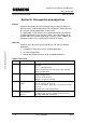
Section E: Appendix Error messages Flying Saw with SIMOTION A4027118-A0414 Starting position to automatic Error for superimposed positioning of the FlyingSawAxis to create "gap" ( _pos ) Details in FS_Var structure under FR_possuperimp_FSA C056 Starting position to automatic Error when positioning the FlyingSawAxis ( _pos ) Details in FS_Var structure under RetDINT_pos_FSA C057 Starting position to automatic Error when positioning the FlyingSawAxis ( _pos ) Details in FS_Var structure under FR_pos_FSA
Section E: Appendix Error messages Flying Saw with SIMOTION Copyright © Siemens AG 2008 All rights reserved Manual_SIMOTION Flying Saw_V1.4.doc ErrorID error code C061 V 1.
Section E: Appendix Error messages Flying Saw with SIMOTION Copyright © Siemens AG 2008 All rights reserved Manual_SIMOTION Flying Saw_V1.4.doc ErrorID error code C091 V 1.
Section E: Appendix Contact partner Flying Saw with SIMOTION 13 A4027118-A0414 Contact partner Applicationcenter SIEMENS Siemens AG Automation & Drives A&D MC PM APC Frauenauracher Str. 80 Erlangen Copyright © Siemens AG 2008 All rights reserved Manual_SIMOTION Flying Saw_V1.4.doc Fax: 09131-98-1297 mailto: applications.erlf@siemens.com V 1.
Section E: Appendix Please help us to become even better Flying Saw with SIMOTION 14 A4027118-A0414 Please help us to become even better A&D MC PM APC Application Center From: Name: Department: City: Telephone: E-Mail: D – 91056 Erlangen Fax: +49 (0) 9131/98–1297 E-Mail: applications@erlf.siemens.