Preface SIMATIC S7-300 CPU 31xC and CPU 31x, Technical data Manual This manual is part of the documentation package with the order number: 6ES7398-8FA10-8BA0 Edition 08/2004 A5E00105475-05 Guide to the S7-300 documentation 1 Operating and display elements 2 Communication 3 Memory concept 4 Cycle and reaction times 5 Technical data of CPU 31xC 6 Technical data of CPU 31x 7 Appendix A
Safety Guidelines This manual contains notices which you should observe to ensure your own personal safety as well as to avoid property damage. The notices referring to your personal safety are highlighted in the manual by a safety alert symbol, notices referring to property damage only have no safety alert symbol. Danger indicates an imminently hazardous situation which, if not avoided, will result in death or serious injury.
Preface Purpose of the Manual This manual contains all the information you will need concerning the configuration, communication, memory concept, cycle, response times and technical data for the CPUs. You will then learn the points to consider when upgrading to one of the CPUs discussed in this manual. Required basic knowledge • To understand this manual, you require a general knowledge of automation engineering. • You should also be accustomed to working with STEP 7 basic software.
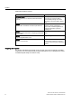
Preface Note There you can obtain the descriptions of all current modules. For new modules, or modules of a more recent version, we reserve the right to include a Product Information containing latest information. Approvals The SIMATIC S7-300 product series has the following approvals: • Underwriters Laboratories, Inc.: UL 508 (Industrial Control Equipment) • Canadian Standards Association: CSA C22.2 No.
Preface Documentation classification This manual is part of the S7-300 documentation package.
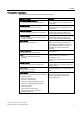
Preface Additional information required: Name of the manual Description Reference Manual Description of the SFCs, SFBs and OBs. System software for S7-300/400 system and standard functions This manual is part of the STEP 7 documentation package. For further information, refer to the STEP 7 Online Help. Manual Description of Industrial Ethernet networks, network configuration, components, installation guidelines for networked automation systems in buildings, etc.
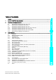
Table of contents Preface ...................................................................................................................................................... iii 1 Guide to the S7-300 documentation ....................................................................................................... 1-1 2 Operating and display elements ............................................................................................................. 2-1 3 2.1 2.1.
Table of contents 4 5 6 viii Memory concept ..................................................................................................................................... 4-1 4.1 4.1.1 4.1.2 4.1.3 4.1.4 4.1.5 Memory areas and retentivity..................................................................................................... 4-1 CPU memory areas....................................................................................................................
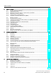
Table of contents 7 A 6.5 CPU 314C-2 PtP and CPU 314C-2 DP ................................................................................... 6-21 6.6 6.6.1 6.6.2 6.6.3 6.6.4 6.6.5 6.6.6 6.6.7 6.6.8 6.6.9 Technical data of the integrated I/O......................................................................................... 6-28 Arrangement and usage of integrated I/Os.............................................................................. 6-28 Analog I/O ..................................
Table of contents Tables Table 1-1 Application area covered by this manual ...................................................................................... iii Table 1-1 Ambient influence on the automation system (AS).................................................................... 1-1 Table 1-2 Galvanic isolation .......................................................................................................................
Table of contents Table 4-1 Retentivity of the RAM ............................................................................................................... 4-2 Table 4-2 Retentive behavior of memory objects (applies to all CPUs with DP/MPI-SS (31x-2 PN/DP) .. 4-3 Table 4-3 Retentive behavior of DBs for CPUs with firmware >= V2.1.0 .................................................. 4-4 Table 4-4 Address areas of system memory .....................................................................
Table of contents Table 7-1 Available MMCs ......................................................................................................................... 7-2 Table 7-2 Maximum number of loadable blocks on the MMC.................................................................... 7-2 Table 7-3 Technical data for the CPU 312................................................................................................. 7-3 Table 7-4 Technical data for the CPU 314...........................
Guide to the S7-300 documentation 1 Overview There you find a guide leading you through the S7-300 documentation. Selecting and configuring Table 1-1 Ambient influence on the automation system (AS) Information on.. is available in ...
Guide to the S7-300 documentation Table 1-3 Communication between sensors/actuators and the PLC Information on.. is available in ...
Guide to the S7-300 documentation Table 1-6 CPU performance Information on.. is available in ...
Guide to the S7-300 documentation Table 1-9 Supplementary features Information on.. is available in ...
2 Operating and display elements 2.1 Operating and display elements: CPU 31xC Operating and display elements of CPU 31xC 1 2 3 SF BF MMC DC5V FRCE RUN STOP RUN STOP MRES 7 6 X1 5 X2 X11 X12 4 The figures show the following CPU elements (1) Status and error displays (2) Slot for the Micro Memory Card (MMC), incl. the ejector (3) Connections of the integrated I/O. (4) Power supply connection (5) 2. Interface X2 (PtP or DP) (6) 1.
Operating and display elements 2.1 Operating and display elements: CPU 31xC The figure below illustrates the integrated digital and analog I/Os of the CPU with open front covers.
Operating and display elements 2.1 Operating and display elements: CPU 31xC Mode selector switch Use the mode selector switch to set the CPU operating mode. Table 2-1 Positions of the mode selector switch Position Meaning Description RUN RUN mode The CPU executes the user program. STOP STOP mode The CPU does not execute a user program. MRES CPU memory reset Mode selector switch position with pushbutton function for CPU memory reset.
Operating and display elements 2.1 Operating and display elements: CPU 31xC 2.1.1 Status and Error Indicators: CPU 31xC LED designation Color Meaning SF red Hardware or software error BF (for CPUs with DP red interface only) Bus error DC5V green 5-V power for CPU and S7-300 bus is OK FRCE yellow Force job is active RUN green CPU in RUN The LED flashes during STARTUP at a rate of 2 Hz, and in HOLD state at 0.5 Hz. STOP yellow CPU in STOP and HOLD or STARTUP The LED flashes at 0.
Operating and display elements 2.2 Operating and display elements: CPU 31x 2.2 Operating and display elements: CPU 31x 2.2.1 Operating and display elements: CPU 312, 314, 315-2 DP: Operating and display elements 1 SF 6 BF MMC DC5V FRCE 5 RUN STOP RUN STOP MRES 2 4 X1 X2 3 The figures show the following CPU elements (1) Slot for the Micro Memory Card (MMC), incl. the ejector (2) 2. Interface X2 (only for CPU 315-2 DP) (3) Power supply connection (4) 1.
Operating and display elements 2.2 Operating and display elements: CPU 31x Slot for the SIMATIC Micro Memory Card (MMC) A SIMATIC Micro Memory Card (MMC) is used as memory module. You can use MMCs as load memory and as portable storage medium. Note These CPUs do not have an integrated load memory and thus require an MMC for operation. Mode selector switch The mode selector switch is used to set the CPU operating mode.
Operating and display elements 2.2 Operating and display elements: CPU 31x 2.2.2 Operating and display elements: CPU 317-2 DP Operating and display elements 1 BF1 2 3 SF BF2 DC5V MMC FRCE RUN STOP 4 RUN STOP MRES 7 6 5 X1 X2 The figures show the following CPU elements (1) Bus error indicator (2) Status and error displays (3) Slot for the Micro Memory Card (MMC), incl. the ejector (4) Mode selector switch (5) Power supply connection (6) 1. Interface X1 (MPI/DP) (7) 2.
Operating and display elements 2.2 Operating and display elements: CPU 31x Slot for the SIMATIC Micro Memory Card (MMC) A SIMATIC Micro Memory Card (MMC) is used as memory module. You can use MMCs as load memory and as portable storage medium. Note These CPUs do not have an integrated load memory and thus require an MMC for operation. Mode selector switch Use the mode selector switch to set the CPU operating mode.
Operating and display elements 2.2 Operating and display elements: CPU 31x 2.2.3 Operating and display elements: CPU 31x-2 PN/DP Operating and display elements 1 BF1 2 3 SF BF2 MMC DC5V FRCE RUN STOP 4 RUN STOP 5 MRES 8 LINK RX / TX 7 MAC-ADD.: X1-X2-X3 X4-X5-X6 6 X1 X2 The figures show the following CPU elements (1) Bus error indicators (2) Status and error displays (3) Slot for the Micro Memory Card (MMC), incl.
Operating and display elements 2.2 Operating and display elements: CPU 31x Slot for the SIMATIC Micro Memory Card (MMC) A SIMATIC Micro Memory Card (MMC) is used as memory module. You can use MMCs as load memory and as portable storage medium. Note These CPUs do not have an integrated load memory and thus require an MMC for operation. Mode selector switch Use the mode selector switch to set the CPU operating mode.
Operating and display elements 2.2 Operating and display elements: CPU 31x 2.2.4 Status and error displays of the CPU 31x General status and error displays Table 2-6 General status and error displays of the CPU 31x LED designation Color Meaning SF red Hardware or software error. DC5V green 5-V power for the CPU and the S7-300 bus FRCE yellow LED is lit: Active force job LED flashes at 2 Hz: Node flash test function (only CPUs with firmware V2.2.
Operating and display elements 2.
Communication 3.1 Interfaces 3.1.1 Multi-Point Interface (MPI) 3 Availability All CPUs described in this manual are equipped with an MPI interface X1. A CPU equipped with an MPI/DP interface is configured and supplied as MPI. To use the DP interface, set DP interface mode in STEP 7. Properties The MPI (Multi-Point Interface) represents the CPU interface for PG/OP connections, or for communication on an MPI subnet. The typical (default) transmission rate of all CPUs is 187.5 kbps. You can also set 19.
Communication 3.1 Interfaces Devices capable of MPI communication • PG/PC • OP/TP • S7-300 / S7-400 with MPI interface • S7-200 (19.2 kbps only) 3.1.2 PROFIBUS DP Availability CPUs with “DP“ name suffix are equipped at least with a DP X2 interface. The 315-2 PN/DP and 317 CPUs are equipped with an MPI/DP X1 interface. A CPU with MPI/DP interface is supplied with a default MPI configuration. You need to set DP mode in STEP 7 if you want to use the DP interface.
Communication 3.1 Interfaces Note (for DP interface in slave mode only) When you disable the Commissioning / Debug mode / Routing check box in the DP interface properties dialog in STEP 7, all user-specific transmission rate settings will be ignored, and the transmission rate of the master is automatically set instead. This disables the routing function at this interface.
Communication 3.1 Interfaces Devices capable of PROFINET (PN) communication • PROFINET IO components (for example, interface module IM 151-3 PN in an ET 200S) • S7-300 / S7-400 with PROFINET interface (for example, CPU 317-2 PN/DP or CP 343-1 PN) • Active network components (a switch, for example) • PG/PC with network card Properties of PROFINET interface X2 Properties IEEE standard 802.3 Connector design RJ45 Transmission speed Max.
Communication 3.1 Interfaces 3.1.4 Point to Point (PtP) Availability CPUs with a “PtP“ name suffix are equipped with a PtP X2 interface. Properties Using the PtP interface of your CPU, you can connect external devices with serial interface. You can operate such a system at transmission rates up to 19.2 kbps in full duplex mode (RS 422), and up to 38.4 kbps in half duplex mode (RS 485). Transmission rate • Half duplex: 38.4 kbps • Full duplex: 19.
Communication 3.2 Communication services 3.2 Communication services 3.2.1 Overview of communication services Selecting the communication service You need to decide on a communication service, based on functionality requirements. Your choice of communication service will have no effect on: • the functionality available, • whether an S7 connection is required or not, and • the time of connecting. The user interface can vary considerably (SFC, SFB, ...
Communication 3.2 Communication services See also Distribution and availability of S7 connection resources (Page 3-29) Connection resources for routing (Page 3-31) 3.2.2 PG communication Properties PG communication is used to exchange data between engineering stations (PG, PC, for example) and SIMATIC modules which are capable of communication. This service is available for MPI, PROFIBUS and Industrial Ethernet subnets. Transition between subnets is also supported.
Communication 3.2 Communication services Reference • Details on SFCs are found in the Instruction list, for more details refer to the STEP 7 Online Help or to the System and Standard Functions Reference Manual. • For further information on communication, refer to the Communication with SIMATIC manual. 3.2.
Communication 3.2 Communication services 3.2.6 Global data communication (MPI only) Properties Global data communication is used for cyclic exchange of global data via MPI subnets (for example, I, Q, M) between SIMATIC S7 CPUs (data exchange without acknowledgement). One CPU broadcasts its data to all other DP CPUs on the MPI subnet. This function is integrated in the CPU operating system. Reduction ratio The reduction ratio specifies the cyclic intervals for GD communication.
Communication 3.2 Communication services GD resources of the CPUs Table 3-4 3.2.7 GD resources of the CPUs Parameters CPU 31xC, 312, 314 CPU 315-2 DP, 315-2 PN/DP, 317 Number of GD circuits per CPU Max. 4 Max. 8 GD packets transmitted per GD circuit Max. 1 Max. 1 GD packets transmitted by all GD circuits Max. 4 Max. 8 GD packets received per GD circuit Max. 1 Max. 1 GD packets received by all GD circuits Max. 4 Max. 8 Data length per GD packet max. 22 bytes max.
Communication 3.2 Communication services Routing network nodes: MPI - DP Gateways between subnets are routed in a SIMATIC station that is equipped with interfaces to the respective subnets. The figure below shows CPU 1 (DP master) acting as router for subnets 1 and 2. PG S7-300 S7-300 CPU (DP master) CPU (DP slave) Subnet 2 (e.g. PROFIBUS DP) Subnet 1 (e.g. MPI) The figure below shows the access to an Ethernet subnet.
Communication 3.2 Communication services Routing network nodes: MPI – DP - Ethernet CPU 1 (e.g.
Communication 3.2 Communication services Requirements • The station modules are "capable of routing" (CPUs or CPs). • The network configuration does not exceed project limits. • The modules have loaded the configuration data containing the latest "knowledge" of the entire network configuration of the project. Reason: All modules participating in the network transition must receive the routing information defining the paths to other subnets.
Communication 3.2 Communication services Routing: Example of a TeleService application The figure below shows the example of an application for remote maintenance of an S7 station using a PG. The connection to other subnets is here established via modem connection. The lower section of the figure shows how to configure this in STEP 7. e.g. 31xC-2DP DP master Real installation e.g. 31xC-2DP DP slave PG TeleService adapter Modem Modem Configuration in STEP 7 Subnet 2 (e.g. PROFIBUS DP) Subnet 1 (e.g.
Communication 3.2 Communication services Reference • on configuring in STEP 7 is found in the Configuring Hardware and Connections in STEP 7 manual • of a basic nature is contained in the Communication with SIMATIC Manual. • on the TeleService adapter can be found on the Internet URL: http://www.ad.siemens.de/support. In the Manual Search section, you can enter the search term A5E00078070 to download the documentation.
Communication 3.2 Communication services 3.2.9 Data consistency Properties A data area is considered consistent, if the operating system can read/write access the data area in a continuous block. Data exchanged collectively between the stations should belong together and originate from a single processing cycle, that is, be consistent.
Communication 3.2 Communication services Objectives in PROFINET The objectives in PROFINET are: • An open Ethernet standard for automation based on Industrial Ethernet Industrial Ethernet and standard Ethernet components can be used together, however, Industrial Ethernet devices are more reliable, and are therefore more suitable for industrial environments (temperature, immunity to noise etc.
Communication 3.2 Communication services Extent of PROFINET CBA and PROFINET IO PROFINET IO and CBA represent two different views of automation devices on Industrial Ethernet.
Communication 3.2 Communication services 3.2.10.
Communication 3.2 Communication services Requirements • CPUs as of Firmware 2.3.0 (for example CPU 315-2 PN/DP) • STEP 7, as of Version 5.3 + Service Pack 1 Reference You will find information on the topic of PROFINET in the following sources: • in the System Description PROFINET • in the From PROFIBUS DP to PROFINET IO programming manual. This manual also lists the new PROFINET blocks and system status lists. See also PROFINET (PN) (Page 3-3) 3.2.10.
Communication 3.2 Communication services Comparison of the System and Standard Functions of PROFINET IO and PROFIBUS DP For CPUs with an integrated PROFINET interface, the table below provides you with an overview of: • System and standard functions for SIMATIC that you may need to replace when converting from PROFIBUS DP to PROFINET IO.
Communication 3.2 Communication services The following table provides you with an overview of the system and standard functions for SIMATIC, whose functionality must be implemented by other functions when converting from PROFIBUS DP to PROFINET IO.
Communication 3.2 Communication services 3.2.10.3 System status lists (SSLs) in PROFINET IO Chapter Content This chapter explains the following: • Which SSLs are intended for PROFINET • Which SSLs are intended for PROFIBUS DP • Which SSLs are intended for both PROFINET IO and PROFIBUS DP Compatibility of the new SSLs For PROFINET IO, it was necessary to create some new SSLs, among other things, because larger configurations are now possible with PROFINET. You can also use these new SSLs with PROFIBUS.
Communication 3.2 Communication services Detailed Information For detailed descriptions of the individual system status lists, refer to the manual System Software for S7-300/400 System and Standard Functions. 3.2.10.4 Open communication via Industrial Ethernet Requirements • CPU 31x-2 PN/DP with firmware version 2.2.0 or higher: • STEP 7 V5.3 + Servicepack 1 or higher Functionality CPUs with Firmware V2.3.
Communication 3.2 Communication services Establishing a connection for communication FB 65 "TCON" establishes communication between the CPU and a communication partner. You can establish up to eight connections. The CPU automatically monitors and holds the active connection. Communication partner A must initiate the connection. When the connection of communication partner A is active, it transmits a request to connect to communication partner B.
Communication 3.3 S7 connections 3.2.10.5 SNMP communication service Availability The SNMP communication service is available for CPUs with integrated PROFINET interface and Firmware 2.3.0 or higher. Properties SNMP (Simple Network Management Protocol) is a standard protocol for TCP/IP networks. Reference For further information on the SNMP communication service and diagnostics with SNMP, refer to the PROFINET System Description. 3.3 S7 connections 3.3.
Communication 3.3 S7 connections Connection points An S7 connection between modules with communication capability is established between connection points. The S7 connection always has two connection points: The active and passive connection points: • The active connection point is assigned to the module that establishes the S7 connection. • The passive connection point is assigned to the module that accepts the S7 connection.
Communication 3.3 S7 connections Assigning connections in the program In S7 basic communication, and in open Industrial Ethernet communication with TCP/IP, the user program establishes the connection. The CPU operating system initiates the connection. S7 basic communication uses the corresponding S7 connections. The open IE communication does not use any S7 connections. The maximum number of eight connections also applies to this type of communication.
Communication 3.3 S7 connections 3.3.3 Distribution and availability of S7 connection resources Distribution of connection resources Table 3-10 Distribution of connections Communication service Distribution PG communication In order to avoid allocation of connection resources being dependent only on the chronological sequence in which various communication services are requested, connection resources can be reserved for these services.
Communication 3.
Communication 3.3 S7 connections 3.3.4 Connection resources for routing Number of connection resources for routing The CPUs with DP interface provide a different number of connection resources for the routing function: Table 3-12 Number of routing connection resources (for DP/PN CPUs) CPU As of firmware version Number of connections for routing 31xC, CPU 31x 2.0.0 Max. 4 317-2 DP 2.1.0 Max. 8 31x-2 PN/DP 2.2.0 Interface X1 configured as: • MPI: Max. 10 • DP master Max.
Communication 3.4 DPV1 3.4 DPV1 New automation and process engineering tasks require the range of functions performed by the existing DP protocol to be extended. In addition to cyclical communication functions, acyclical access to non-S7 field devices is another important requirement of our customers, and was implemented in the standard EN 50170. In the past, acyclical access was only possible with S7 slaves. The distributed I/O standard EN 50170 has been further developed.
Communication 3.4 DPV1 Interrupt blocks with DPV1 functionality Table 3-13 Interrupt blocks with DPV1 functionality OB Functionality OB 40 Process interrupt OB 55 Status interrupt OB 56 Update interrupt OB 57 Vendor-specific interrupt OB 82 Diagnostic interrupt Note You can now also use organizational blocks OB40 and OB82 for DPV1 interrupts.
Communication 3.
4 Memory concept 4.1 Memory areas and retentivity 4.1.1 CPU memory areas The three memory areas of your CPU: Memory of the CPU CPU Loading memory (located on the MMC) MMC System memory Working memory Load memory The load memory is located on a Micro Memory Card (MMC). The size of the load memory corresponds exactly to the size of the MMC. It is used to store code blocks, data blocks and system data (configuration, connections, module parameters, etc.).
Memory concept 4.1 Memory areas and retentivity System memory The RAM system memory is integrated in the CPU and cannot be expanded. It contains • the address areas for address area memory bits, timers and counters • the process image of the I/Os • local data RAM The RAM is integrated in the CPU and cannot be extended. It is used to run the code and process user program data. Programs only run in RAM and system memory. Table 4-1 4.1.
Memory concept 4.1 Memory areas and retentivity Retentive data in RAM Therefore, the contents of retentive DBs are always retentive at restart and POWER ON/OFF. CPUs V2.1.0 or higher also support volatile DBs (the volatile DBs are initialized at restart of POWER OFF-ON with their initial values from load memory.) See also Properties of the Micro Memory Card (MMC) (Page 4-9) 4.1.
Memory concept 4.1 Memory areas and retentivity Retentive behavior of a DB for CPUs with firmware >= V2.1.0 For these CPUs you can specify in STEP 7 (beginning with version 5.2 + SP 1), or at SFC 82 CREA_DBL (parameter ATTRIB -> NON_RETAIN bit), whether a DB at POWER ON/OFF or RUN-STOP • keeps the actual values (retentive DB), or • accepts the initial values from load memory (non-retentive DB) Table 4-3 Retentive behavior of DBs for CPUs with firmware >= V2.1.
Memory concept 4.1 Memory areas and retentivity 4.1.4 Address areas of system memory System memory of the S7 CPUS is organized in address areas (refer to the table below). In a corresponding operation of your user program, you address data directly in the relevant address area.
Memory concept 4.1 Memory areas and retentivity Process image update The operating system updates the process image periodically. The figure below shows the sequence of this operation within a cycle. Startup Startup program Processing the user program (OB 1) and all programs called inside of it. PII User program Cycle time PIO Reading the inputs from the modules and refreshing the data in the process image of the inputs. Writing the process image of the outputs into the modules.
Memory concept 4.1 Memory areas and retentivity Configurable process image with CPU317 (FW V2.3.0 or higher) IN STEP 7, you can define a user-specific size of the I/O process images between 0 to 2048 for a CPU317, FW V2.3.0 or higher. Note the information below: Note Currently, the dynamic setting of the process image only affects its update at the scan cycle control point.
Memory concept 4.1 Memory areas and retentivity Local data Local data store: • the temporary variables of code blocks • the start information of the OBs • transfer parameters • intermediate results Temporary Variables When you create blocks, you can declare temporary variables (TEMP) which are only available during block execution and then overwritten again. These local data have fixed length in each OB. Local data must be initialized prior to the first read access.
Memory concept 4.1 Memory areas and retentivity 4.1.5 Properties of the Micro Memory Card (MMC) The MMC as memory module for the CPU The memory module used on your CPU is a SIMATIC Micro Memory Card (MMC.) You can use MMCs as load memory or as a portable storage medium. Note The CPU requires the MMC for operation.
Memory concept 4.1 Memory areas and retentivity MMC copy protection Your MMC has an internal serial number that provides copy protection at user level. You can read this serial number from the SSL partial list 011CH index 8 using SFC 51 "RDSYSST." You can then program a STOP command, for example, in a copy-protected block if the expected and actual serial numbers of your MCC do not tally. Reference • SSL partial list in the instruction list, or • in the manual System and Standard Functions.
Memory concept 4.2 Memory functions 4.2 Memory functions 4.2.1 General: Memory functions Memory functions Memory functions are used to generate, modify or delete entire user programs or specific blocks. You can also ensure that your project data are retained by archiving these. If there is... You created a new user program, use a PG/ PC to download the complete program to MMC. 4.2.
Memory concept 4.2 Memory functions Note This function is only permitted when the CPU is in STOP mode. Load memory is cleared if the load operation could not be completed due to power loss or illegal block data. 4.2.3 Handling with modules 4.2.3.1 Download of new blocks or delta downloads There are two ways to download additional user blocks or download deltas: • Download of blocks: You already created a user program and downloaded it to the CPU via MMC.
Memory concept 4.2 Memory functions 4.2.3.3 Deleting blocks Deleting blocks When you delete a block, it is deleted from load memory. In STEP 7, you can also delete blocks with the user program (DBs also with SFC 23 "DEL_DB"). RAM used by this block is released. 4.2.3.4 Compressing blocks Compressing blocks When data are compressed, gaps which have developed between memory objects in load memory/RAM as a result of load/delete operations will be eliminated.
Memory concept 4.2 Memory functions Restart (warm start) • All retentive DBs retain their actual value (non-retentive DBs are also supported by CPUs with Firmware >= V2.1.0. Non-retentive DBs receive their initial values). • The values of all retentive M, C, T are retained. • All non-retentive user data are initialized: – M, C, T, I, O with "0" • All run levels are initialized. • The process images are deleted.
Memory concept 4.2 Memory functions 4.2.5 Recipes Introduction A recipe represents a collection of user data. You can implement a simple recipe concept using static DBs. In this case, the recipes should have the same structure (length). One DB should exist per recipe. Processing sequence Recipe is written to load memory: • The various data records of recipes are created as static DBs in STEP 7 and then downloaded to the CPU. Therefore, recipes only use load memory, rather than RAM.
Memory concept 4.2 Memory functions Note As a precaution against loss of data, always make sure that you do not exceed the maximum number of delete/write operations. Also refer to the SIMATIC Micro Memory Card (MMC) section in the "Structure and Communication Connections of a CPU" chapter. Caution Data on a SIMATIC Micro Memory Card can be corrupted if you remove the card while it is being accessed by a write operation.
Memory concept 4.2 Memory functions 4.2.6 Measured value log files Introduction Measured values are generated when the CPU executes the user program. These values are to be logged and analyzed. Processing sequence Acquisition of measured values: • The CPU writes all measured values to a DB (for alternating backup mode in several DBs) which is located in RAM.
Memory concept 4.2 Memory functions The data written to load memory are portable and retentive on CPU memory reset. Evaluation of measured values: • Measured value DBs saved to load memory can be uploaded and evaluated by other communication partners (PG, PC, for example). Note The active system functions SFC 82 to 84 (current access to the MMC) have a distinct influence on PG functions (block status, variable status, load block, upload, open, for example).
Memory concept 4.2 Memory functions 4.2.7 Backup of project data to a Micro Memory Card (MMC) Function principle Using the Save project to Memory Card and Fetch project from Memory Card functions, you can save all project data to a SIMATIC Micro Memory Card, and retrieve these at a later time. For this operation, the SIMATIC Micro Memory Card can be located in a CPU or in the MMC adapter of a PG or PC.
Memory concept 4.
Cycle and reaction times 5.1 5 Overview Overview This section contains detailed information about the following topics: • Cycle time • Reaction time • Interrupt response time • Sample calculations Reference: Cycle time You can view the cycle time of your user program on the PG. For further information, refer to the STEP 7 Online Help, or to the Configuring Hardware and Connections in STEP 7 Manual Reference: Execution time can be found in the S7-300 Instruction List for CPUs 31xC and 31x.
Cycle and reaction times 5.2 Cycle time 5.2 Cycle time 5.2.1 Overview Introduction This section explains what we mean by the term "cycle time", what it consists of, and how you can calculate it. Meaning of the term cycle time The cycle time represents the time that an operating system needs to execute a program, that is, one OB 1 cycle, including all program sections and system activities interrupting this cycle. This time is monitored.
Cycle and reaction times 5.2 Cycle time Sequence of cyclic program processing The table and figure below show the phases in cyclic program processing. Table 5-1 Cyclic program processing Step Sequence 1 The operating system initiates cycle time monitoring. 2 The CPU copies the values of the process image of outputs to the output modules. 3 The CPU reads the status at the inputs of the input modules and then updates the process image of inputs.
Cycle and reaction times 5.2 Cycle time Extending the cycle time Always make allowances for the extension of the cycle time of a user program due to: • Time-based interrupt processing • Process interrupt processing • Diagnostics and error processing • Communication with PGs, Operator Panels (OPs) and connected CPs (for example, Ethernet, PROFIBUS DP) • Testing and commissioning such as, e.g. status/controlling of variables or block status functions.
Cycle and reaction times 5.2 Cycle time 5.2.2 Calculating the cycle time Introduction The cycle time is derived from the sum of the following influencing factors. Process image update The table below shows the time a CPU requires to update the process image (process image transfer time). The times specified might be prolonged as a result of interrupts or CPU communication.
Cycle and reaction times 5.2 Cycle time Table 5-4 CPU 31x: Data for calculating the process image (PI) transfer time Const.
Cycle and reaction times 5.2 Cycle time Operating system processing time at the scan cycle checkpoint The table below shows the operating system processing time at the scan cycle checkpoint of the CPUs. These times are calculated without taking into consideration times for: • Testing and commissioning routines, e.g.
Cycle and reaction times 5.2 Cycle time Extension of the cycle time due to error Table 5-8 Cycle time extension as a result of errors Type of error Programming errors I/O access errors 312C 600 μs 600 μs 313C 400 μs 400 μs 313C2 400 μs 400 μs 314C-2 400 μs 400 μs 312 600 μs 600 μs 314 400 μs 400 μs 315 400 μs 400 μs 317 100 μs 100 μs The interrupt OB processing time must be added to this extended time.
Cycle and reaction times 5.2 Cycle time Maximum cycle time In STEP 7 you can modify the default maximum cycle time. OB80 is called on when this time expires. In this block you can specify the CPUs response to this timeout error. The CPU switches to STOP mode if OB80 does not exist in its memory. 5.2.
Cycle and reaction times 5.2 Cycle time Physical cycle time depending on communication load The figure below describes the non-linear dependency of the physical cycle time on communication load. In our sample we have chosen a cycle time of 10 ms. Cycle time 30 ms The communication load can be defined in this area.
Cycle and reaction times 5.2 Cycle time 5.2.5 Cycle time extension as a result of testing and commissioning functions Runtimes The runtimes of the testing and commissioning functions are operating system runtimes, so they are the same for every CPU. Initially, there is no difference between process mode and testing mode. How the cycle time is extended as a result of active testing and commissioning functions is shown in the table below.
Cycle and reaction times 5.2 Cycle time Note The use of CBA with cyclical PROFINET interconnections requires the use of switches to maintain the performance data. 100-Mbit full-duplex operation is mandatory with cyclical PROFINET interconnections. The following graphic shows the configuration that was used for the measurements. HMI/OPC Industrial Ethernet Number of observed interconnections in SIMATIC iMAP or OPC: 200 PROFINET remote node 1 ...
Cycle and reaction times 5.2 Cycle time Additional marginal conditions The maximum cycle load through communication in the measurement is 20 %.
Cycle and reaction times 5.3 Response time 5.3 Response time 5.3.1 Overview Definition of response time The response time is the time between the detection of an input signal and the change of a linked output signal. Fluctuation width The physical response time lies between the shortest and the longest response time. You must always reckon with the longest response time when configuring your system.
Cycle and reaction times 5.3 Response time DP cycle times in the PROFIBUS DP network If you have configured your PROFIBUS DP master system in STEP 7, STEP 7 calculates the typical DP cycle time to be expected. You can then view the DP cycle time of your configuration on the PG. The figure below gives you an overview of the DP cycle time. In this example, let us assume that the data of each DP slave has an average length of 4 bytes. Bus runtime 17 ms 7 ms Transmission rate 1.
Cycle and reaction times 5.3 Response time 5.3.2 Shortest response time Conditions for the shortest response time The figure below shows the conditions under which the shortest response time is reached. CCP (OS) Delay of inputs PIO Response time PII User program Immediately before reading in the PII, the status of the monitored input changes. This change of the input signal is still included in the PII. The change of the input signal is processed by the application program.
Cycle and reaction times 5.3 Response time 5.3.3 Longest response time Conditions for the longest response time The figure below shows the conditions under which the longest response time is reached. CCP (OS) Delay of inputs + 2 x DP cycle time at PROFIBUS DP PIO PII While reading in the PII, the status of the monitored input changes. This change of the input signal is not included in the PII any longer. Response time CCP (OS) PIO The change of the input signal is included in the PII.
Cycle and reaction times 5.3 Response time Calculation The (longest) response time is the sum of: Table 5-11 Formula: Longest response time 2 x process image transfer time for the inputs + 2 x process image transfer time for the outputs + 2 x program processing time + 2 × operating system processing time + 2 x program processing time + 4 x PROFINET IO update time (only if PROFINET IO is used.) + 4 x DP cycle time on PROFIBUS DP (only if PROFIBUS DP is used.
Cycle and reaction times 5.4 Calculating method for calculating the cycle/response time 5.4 Calculating method for calculating the cycle/response time Introduction This section gives you an overview of how to calculate the cycle/response time. Cycle time 1. Determine the user program runtime with the help of the Instruction list. 2. Multiply the calculated value by the CPU-specific factor from the table Extension of user program processing time. 3. Calculate and add the process image transfer time.
Cycle and reaction times 5.4 Calculating method for calculating the cycle/response time Response time Table 5-12 Calculating the response time Shortest response time Longest response time - Multiply the physical cycle time by factor 2. Now add I/O delay. Now add the I/O delay plus the DP cycle times on PROFIBUS-DP or the PROFINET IO update times. The result is the shortest response time. The result is the longest response time.
Cycle and reaction times 5.5 Interrupt response time 5.5 Interrupt response time 5.5.1 Overview Definition of interrupt response time The interrupt response time is the time that expires between the first occurrence of an interrupt signal and the call of the first interrupt OB instruction. Generally valid: Higherpriority interrupts take priority.
Cycle and reaction times 5.5 Interrupt response time Calculation The formula below show how you can calculate the minimum and maximum interrupt response times.
Cycle and reaction times 5.5 Interrupt response time Process interrupt processing Process interrupt processing begins after process interrupt OB40 is called. Higher-priority interrupts stop process interrupt processing. Direct I/O access is executed during runtime of the instruction. After process interrupt processing has terminated, cyclic program execution continues or further interrupt OBs of equal or lower priority are called and processed. See also Overview (Page 5-1) 5.5.
Cycle and reaction times 5.6 Sample calculations 5.6 Sample calculations 5.6.1 Example of cycle time calculation Installation You have configured an S7300 and equipped it with following modules in rack "0": • a CPU 314C-2 • 2 digital input modules SM 321; DI 32 x 24 VDC (4 bytes each in the PI) • 2 digital output modules SM 322; DO 32 x 24 VDC/0.5 A (4 bytes each in the PI) User program According to the Instruction List, the user program runtime is 5 ms. There is no active communication.
Cycle and reaction times 5.6 Sample calculations Calculating the longest response time Longest response time: 6.8 ms x 2 = 13.6 ms. • I/O delay can be neglected. • Neither PROFIBUS DP, nor PROFINET IO are being used, so you do not have to make allowances for any DP cycle times on PROFIBUS DP or for PROFINET IO update times. • Interrupts are not processed. 5.6.
Cycle and reaction times 5.6 Sample calculations Calculating the physical cycle time Under consideration of communication load: 12.5 ms * 100 / (100-40) = 20.8 ms. Thus, under consideration of time-sharing factors, the actual cycle time is 21 ms. Calculation of the longest response time • Longest response time = 21 ms * 2 = 42 ms. • I/O delay – The maximum delay of the input digital module SM 321; DI 32 x 24 VDC is 4.8 ms per channel.
Cycle and reaction times 5.6 Sample calculations 5.6.3 Example of interrupt response time calculation Installation You have assembled an S7-300, consisting of one CPU 314C-2 and four digital modules in the CPU rack. One of the digital input modules is an SM 321; DI 16 x 24 VDC; with process/diagnostic interrupt function. You have enabled only the process interrupt in your CPU and SM parameter configuration. You decided not to use time-controlled processing, diagnostics or error handling.
Cycle and reaction times 5.
Technical data of CPU 31xC 6.1 General technical data 6.1.1 Dimensions of CPU 31xC 6 Each CPU features the same height and depth, only the width dimensions differ. • Height: 125 mm • Depth: 115 mm, or 180 mm with opened front cover.
Technical data of CPU 31xC 6.1 General technical data 6.1.
Technical data of CPU 31xC 6.2 CPU 312C 6.2 CPU 312C Technical data Table 6-3 Technical data of CPU 312C Technical data CPU and version Order number 6ES7 312-5BD01-0AB0 • Hardware version 01 • Firmware version V2.0 • Associated programming package STEP 7 as of V 5.2 + SP 1 (please use previous CPU for STEP 7 V 5.1 + SP 3 or later) Memory RAM • Integrated 16 KB • Expandable No Load memory Plugged in with MMC (max.
Technical data of CPU 31xC 6.2 CPU 312C Technical data IEC Timers Yes • Type SFB • Number unlimited (limited only by RAM size) Data areas and their retentivity Flag bits 128 bytes • Retentive memory Configurable • Default retentivity MB0 to MB15 Clock flag bits 8 (1 byte per flag bit) Data blocks Max. 511 (DB 1 to DB 511) • Length Local data per priority class max. 16 KB max.
Technical data of CPU 31xC 6.2 CPU 312C Technical data Assembly Racks Max. 1 Modules per rack Max. 8 Number of DP masters • Integrated None • Via CP Max. 1 Number of function modules and communication processors you can operate • FM Max. 8 • CP (PtP) Max. 8 • CP (LAN) Max.
Technical data of CPU 31xC 6.2 CPU 312C Technical data Block status Yes Single step Yes Breakpoints 2 Diagnostic buffer Yes • Number of entries (not configurable) Max. 100 Communication functions PG/OP communication Yes Global data communication Yes • Number of GD circuits 4 • Number of GD packets – Sending stations – Receiving stations Max. 4 Length of GD packets – Consistent data max. 22 bytes • S7 basic communication • • User data per request Consistent data Max. 4 Max.
Technical data of CPU 31xC 6.2 CPU 312C Technical data Functionality • MPI Yes • PROFIBUS DP No • Point-to-point communication No MPI Services • PG/OP communication Yes • Routing No • Global data communication Yes • S7 basic communication Yes • S7 communication – As server – As client Yes No • Transmission rates max. 187.
Technical data of CPU 31xC 6.3 CPU 313C Technical data I2t 0.7 A2s External fusing of power supply lines (recommended) LS switch Type C min. 2 A, LS switch Type B min. 4 A Power loss Typically 6 W Reference In Chapter Specifications of the integrated I/O you can find • the specifications of integrated I/Os under Digital inputs of CPUs 31xC and Digital outputs of CPUs 31xC. • the block diagrams of the integrated I/Os under Arrangement and usage of integrated I/Os. 6.
Technical data of CPU 31xC 6.
Technical data of CPU 31xC 6.3 CPU 313C Technical data Address areas (I/O) Total I/O address area max. 1024 bytes/1024 bytes (can be freely addressed) I/O process image 128 bytes/128 bytes Digital channels Max. 1016 • of those local Max. 992 • Integrated channels 24 DI / 16 DO Analog channels Max. 253 • of those local Max. 248 • Integrated channels 4 + 1 AI / 2 AO Assembly Racks Max. 4 Modules per rack max. 8; max. 7 in rack 3 Number of DP masters • Integrated None • via CP Max.
Technical data of CPU 31xC 6.3 CPU 313C Technical data Process diagnostics messages • Simultaneously enabled interrupt S blocks Yes Max. 20 Testing and commissioning functions Status/control variables Yes • Variables Inputs, outputs, memory bits, DBs, timers, counters • Number of variables – of those as status variable – of those as control variable Max. 30 Forcing Max. 30 Max. 14 Yes • Variables Inputs, outputs • Number of variables Max.
Technical data of CPU 31xC 6.3 CPU 313C Technical data can be used for • • • PG communication – Reserved (default) – Configurable Max. 7 OP communication – Reserved (default) – Configurable Max. 7 S7 basic communication – Reserved (default) – Configurable Max. 4 Routing 1 from 1 to 7 1 from 1 to 7 4 from 0 to 4 No Interfaces 1st interface Type of interface Integrated RS485 interface Physics RS 485 electrically isolated No Interface power supply (15 to 30 VDC) Max.
Technical data of CPU 31xC 6.3 CPU 313C Technical data Integrated I/O • Default addresses of the integrated – Digital inputs – Digital outputs – Analog inputs – Analog outputs 124.0 to 126.7 124.0 to 125.7 752 to 761 752 to 755 Integrated functions Counters 3 channels (see the Manual Technological Functions) Frequency counters 3 channels, max. 30 kHz (see the Manual Technological Functions) Pulse outputs 3 channels for pulse width modulation, max. 2.
Technical data of CPU 31xC 6.4 CPU 313C-2 PtP and CPU 313C-2 DP 6.4 CPU 313C-2 PtP and CPU 313C-2 DP Technical data Table 6-5 Technical data for CPU 313C-2 PtP/ CPU 313C-2 DP Technical data CPU 313C-2 PtP CPU 313C-2 DP CPU and version CPU 313C-2 PtP CPU 313C-2 DP Order number 6ES7 313-6BE01-0AB0 6ES7 313-6CE01-0AB0 • Hardware version 01 01 • Firmware version V2.0.0 V2.0.0 Associated programming package Memory STEP 7 as of V 5.2 + SP 1 STEP 7 as of V 5.
Technical data of CPU 31xC 6.4 CPU 313C-2 PtP and CPU 313C-2 DP Technical data CPU 313C-2 PtP CPU 313C-2 DP Data areas and their retentivity CPU 313C-2 PtP CPU 313C-2 DP Flag bits 256 bytes • Retentive memory • Default retentivity Configurable MB0 to MB15 Clock flag bits 8 (1 byte per flag bit) Data blocks Max. 511 (DB 1 to DB 511) • Length max. 16 KB Local data per priority class max.
Technical data of CPU 31xC 6.4 CPU 313C-2 PtP and CPU 313C-2 DP Technical data CPU 313C-2 PtP CPU 313C-2 DP Number of function modules and communication processors you can operate • FM Max. 8 • CP (PtP) Max. 8 • CP (LAN) Max.
Technical data of CPU 31xC 6.4 CPU 313C-2 PtP and CPU 313C-2 DP Technical data CPU 313C-2 PtP CPU 313C-2 DP Communication functions CPU 313C-2 PtP CPU 313C-2 DP PG/OP communication Yes Global data communication Yes • Number of GD circuits 4 • Number of GD packets – Sending stations – Receiving stations Max. 4 Length of GD packets – Consistent data max. 22 bytes • S7 basic communication • User data per request – Consistent data Max. 4 Max. 4 22 bytes Yes (server) max.
Technical data of CPU 31xC 6.
Technical data of CPU 31xC 6.
Technical data of CPU 31xC 6.4 CPU 313C-2 PtP and CPU 313C-2 DP Technical data CPU 313C-2 PtP CPU 313C-2 DP Integrated functions Counters 3 channels (see the Manual Technological Functions) Frequency counters 3 channels, max. 30 kHz (see the Manual Technological Functions) Pulse outputs 3 channels for pulse width modulation, max. 2.
Technical data of CPU 31xC 6.5 CPU 314C-2 PtP and CPU 314C-2 DP 6.5 CPU 314C-2 PtP and CPU 314C-2 DP Technical data Table 6-6 Technical data of CPU 314C-2 PtP and CPU 314C-2 DP Technical data CPU 314C-2 PtP CPU 314C-2 DP CPU and version CPU 314C-2 PtP CPU 314C-2 DP Order number 6ES7 314-6BF01-0AB0 6ES7 314-6CF01-0AB0 • Hardware version 01 01 • Firmware version V2.0.0 V2.0.0 Associated programming package Memory STEP 7 as of V 5.2 + SP 1 STEP 7 as of V 5.
Technical data of CPU 31xC 6.5 CPU 314C-2 PtP and CPU 314C-2 DP Technical data CPU 314C-2 PtP CPU 314C-2 DP Data areas and their retentivity CPU 314C-2 PtP CPU 314C-2 DP Flag bits 256 bytes • Retentive memory • Default retentivity Configurable MB0 to MB15 Clock flag bits 8 (1 byte per flag bit) Data blocks Max. 511 (DB 1 to DB 511) • Length max. 16 KB Local data per priority class max.
Technical data of CPU 31xC 6.5 CPU 314C-2 PtP and CPU 314C-2 DP Technical data CPU 314C-2 PtP CPU 314C-2 DP Number of function modules and communication processors you can operate • FM Max. 8 • CP (PtP) Max. 8 • CP (LAN) Max.
Technical data of CPU 31xC 6.5 CPU 314C-2 PtP and CPU 314C-2 DP Technical data CPU 314C-2 PtP CPU 314C-2 DP Communication functions CPU 314C-2 PtP CPU 314C-2 DP PG/OP communication Yes Global data communication Yes • Number of GD circuits 4 • Number of GD packets – Sending stations – Receiving stations Max. 4 Length of GD packets – Consistent data max. 22 bytes • S7 basic communication • User data per request – Consistent data Max. 4 Max. 4 22 bytes Yes max.
Technical data of CPU 31xC 6.5 CPU 314C-2 PtP and CPU 314C-2 DP Technical data CPU 314C-2 PtP CPU 314C-2 DP MPI Number of connections 12 Services • PG/OP communication Yes • Routing No • Global data communication Yes • S7 basic communication Yes • S7 communication – As server – As client Yes Transmission rates max. 187.
Technical data of CPU 31xC 6.
Technical data of CPU 31xC 6.5 CPU 314C-2 PtP and CPU 314C-2 DP Technical data CPU 314C-2 PtP CPU 314C-2 DP Integrated functions Counters 4 channels (see the Manual Technological Functions) Frequency counters 4 channels, max. 60 kHz (see the Manual Technological Functions) Pulse outputs 4 channels for pulse width modulation, max. 2.
Technical data of CPU 31xC 6.6 Technical data of the integrated I/O 6.6 Technical data of the integrated I/O 6.6.1 Arrangement and usage of integrated I/Os Introduction Integrated I/Os of CPUs 31xC can be used for technological functions or as standard I/O. The figures below illustrate possible usage of I/Os integrated in the CPUs. Reference Further information on integrated I/O is found in the Manual Technical Functions.
Technical data of CPU 31xC 6.
Technical data of CPU 31xC 6.
Technical data of CPU 31xC 6.
Technical data of CPU 31xC 6.6 Technical data of the integrated I/O CPU 313C/314C-2: Pin-out of the integrated AI/AO and DI (connector X11) X11 1) Positioning Standard V I C V I C V I C V I C AI (Ch0) AI (Ch1) AI (Ch2) AI (Ch3) PT 100 (Ch4) AO (Ch0) AO (Ch1) V A V A Control output 0 1 2 3 4 5 6 7 8 9 10 11 12 13 14 15 16 17 18 19 20 PEWx+0 PEWx+2 PEWx+4 DI+2.0 DI+2.1 DI+2.2 DI+2.3 DI+2.4 DI+2.5 DI+2.6 DI+2.
Technical data of CPU 31xC 6.6 Technical data of the integrated I/O Simultaneous usage of technological functions and standard I/O Technological functions and standard I/O can be used simultaneously with appropriate hardware. For example, you can use all digital inputs not used for counting functions as standard DI. Read access to inputs used by technological functions is possible. Write access to outputs used by technological functions is not possible.
Technical data of CPU 31xC 6.6 Technical data of the integrated I/O 6.6.2 Analog I/O Wiring of the current/voltage inputs The figure below shows the wiring diagram of the current/voltage inputs operated with 2-/4-wire measuring transducers. Al0: Pin 2 to 4 + 2-wire signal converter - AI2u 8 AI2I 9 + 10 - AI2c AI1: Pin 5 to 7 Al2: Pin 8 to 10 + 24 V Al3: Pin 11 to 13 20 MANA M We recommend connecting AIxC with MANA using a bridge.
Technical data of CPU 31xC 6.6 Technical data of the integrated I/O Measurement principle 31xC CPUs use the measurement principle of actual value encoding. Here, they operate with a sampling rate of 1 kHz. That is, a new value is available at the peripheral input word register once every millisecond. This value can then be read via user program (e.g. L PEW). The "previous" value is read again if access times are shorter than 1 ms.
Technical data of CPU 31xC 6.6 Technical data of the integrated I/O Input filters (software filter) The current / voltage inputs have a software filter for the input signals which can be programmed with STEP 7. It filters the configured interference frequency (50/60 Hz) and multiples thereof. The selected interference suppression also determines the integration time.
Technical data of CPU 31xC 6.6 Technical data of the integrated I/O In the two graphics below we illustrate how the 50 Hz and 60 Hz interference suppression work Example of a 50-Hz parasitic frequency suppression (integration time corresponds to 20 ms) 1.05 ms 1.05 ms 1.05 ms Value 1 Value 2 Value 3 Cycle 1 ... 1.05 ms 1.05 ms Value 19 Value 20 1 averaged measured value 1.05 ms 1.05 ms 1.05 ms Value 1 Value 2 Value 3 Cycle 2 ... 1.05 ms 1.
Technical data of CPU 31xC 6.6 Technical data of the integrated I/O Example of a 60-Hz parasitic frequency suppression (integration time corresponds to 16.7 ms) 1.05 ms 1.05 ms 1.05 ms Value 1 Value 2 Value 3 Cycle 1 ... 1.05 ms 1.05 ms Value 16 Value 17 1 averaged measured value 1.05 ms 1.05 ms 1.05 ms Value 1 Value 2 Value 3 Cycle 2 ... 1.05 ms 1.
Technical data of CPU 31xC 6.6 Technical data of the integrated I/O 6.6.3 Configuration Introduction You configure the integrated I/O of CPU 31xC with STEP 7. Always make these settings when the CPU is in STOP. The generated parameters are downloaded from the PG to the S7-300 and written to CPU memory . You can also choose to change the parameters at SFC 55 in the user program (see the Reference Manual System and Standard Functions). Refer to the structure of record 1 for the respective parameters.
Technical data of CPU 31xC 6.6 Technical data of the integrated I/O Byte 0 0 7 Bit-Nr. Interrupt input DI +0.0 Interrupt input DI +0.1 Interrupt input DI +0.7 Byte 1 0 7 Bit-Nr. Interrupt input DI +1.0 Interrupt input DI +1.1 Interrupt input DI +1.7 Byte 2 0 7 Bit-Nr. Interrupt input DI +2.0 Interrupt input DI +2.1 Interrupt input DI +2.7 0: deactivated 1: rising edge Default setting: Byte 3 reserved Byte 4 0 7 Bit-Nr. Interrupt input DI +0.0 Interrupt input DI +0.
Technical data of CPU 31xC 6.6 Technical data of the integrated I/O Parameters of standard DO There are no parameters for standard digital outputs. Parameters of standard AI The table below gives you an overview of the parameters for standard analog inputs. Table 6-9 Parameters of standard AI Parameters Value range Default Range of efficiency Integration time (ms) 2,5/16,6/20 20 Channel Interference suppression (Hz) 400/60/50 50 Channel Disabled/ +/- 20 mA/ 0 ... 20 mA/ 4 ...
Technical data of CPU 31xC 6.6 Technical data of the integrated I/O Parameters of standard AO The table below gives you an overview of standard analog output parameters (see also Chapter 4.3 in the Module Data Reference Manual). Table 6-10 Parameters of standard AO Parameters Value range Default Range of efficiency Output range Disabled/ +/- 20 mA/ 0 ... 20 mA/ 4 ... 20 mA/ +/- 10 V/ 0 ...
Technical data of CPU 31xC 6.6 Technical data of the integrated I/O %\WH %LW 1U reserved reserved %\WH %LW 1U Parasitic frequency suppression integration time of channel AI 0 Parasitic frequency suppression integration time of channel AI 1 Parasitic frequency suppression integration time of channel AI 2 Parasitic frequency suppression integration time of channel AI 3 % PV +] % PV +] % PV +] % Default setting: 0 Bit no.
Technical data of CPU 31xC 6.
Technical data of CPU 31xC 6.6 Technical data of the integrated I/O 6.6.4 Interrupts Interrupt inputs All digital inputs of the on-board I/O of CPUs 31xC can be used as interrupt inputs. You can specify interrupt behavior for each individual input in your parameter declaration.
Technical data of CPU 31xC 6.6 Technical data of the integrated I/O 31 30 29 28 27 26 25 24 23 … 16 15 … 8 7 6 5 4 3 2 1 Bit no. reserved PRAL from E124.0 PRAL from E124.7 PRAL from E125.0 PRAL from E125.7 PRAL from E126.0 PRAL from E126.7 PRAL: process interrupt Inputs are designated with default addresses. Figure 6-9 Displaying the statuses of CPU 31xC interrupt inputs PRAL: process interrupt The inputs are assigned default addresses. 6.6.
Technical data of CPU 31xC 6.6 Technical data of the integrated I/O Technical data Table 6-12 Technical data of digital inputs Technical data CPU 312C CPU 313C CPU 313C-2 CPU 314C-2 Module-specific data CPU 312C CPU 313C CPU 313C-2 CPU 314C-2 Number of inputs 10 24 16 24 8 12 12 16 • Number of these inputs which can be used for technological functions Cable length • Unshielded • Shielded For standard DI: Max. 600 m For technological functions: No For standard DI: Max.
Technical data of CPU 31xC 6.6 Technical data of the integrated I/O Technical data Data for the selection of an encoder for standard DI CPU 312C CPU 313C CPU 313C-2 CPU 314C-2 CPU 312C CPU 313C CPU 313C-2 CPU 314C-2 Input voltage • Rated value 24 VDC • For signal "1" 15 V to 30 V • For signal "0" -3 V to 5 V Input current • For signal "1" Typically 9 mA Delay of standard inputs • Configurable Yes (0.1 / 0.
Technical data of CPU 31xC 6.6 Technical data of the integrated I/O Technical data Table 6-13 Technical data of digital outputs Technical data CPU 312C CPU 313C CPU 313C-2 CPU 314C-2 Module-specific data CPU 312C CPU 313C CPU 313C-2 CPU 314C-2 Number of outputs 6 16 16 16 2 4 4 4 • Of those are fast outputs Caution: You cannot connect the high-speed outputs of your CPU in parallel. Cable length • Unshielded • Shielded Max. 600 m Max.
Technical data of CPU 31xC 6.6 Technical data of the integrated I/O Technical data Data for the selection of an actuator for standard DI CPU 312C CPU 313C CPU 313C-2 CPU 314C-2 CPU 312C CPU 313C CPU 313C-2 CPU 314C-2 Output voltage • For signal "1" Min. L+ (-0.8 V) Output current • • For signal "1" – Rated value – Permitted range 0,5 A For signal "0" (residual current) Max. 0.5 mA 5 mA to 600 mA Load impedance range 48 Ω to 4 kΩ Lamp load Max.
Technical data of CPU 31xC 6.6 Technical data of the integrated I/O 6.6.8 Analog inputs Introduction This chapter contains the specifications for analog outputs of CPUs 31xC. The table includes the following CPUs: • CPU 313C • CPU 314C-2 DP • CPU 314C-2 PtP Technical data Table 6-14 Technical data of analog inputs Technical data Module-specific data Number of inputs 4 channels with current/voltage input 1 channel with resistance input Cable length • Shielded Max.
Technical data of CPU 31xC 6.6 Technical data of the integrated I/O Technical data Time constant of the input filter 0,38 ms Basic processing time 1 ms Interference suppression, error limits Interference voltage suppression for f = nx (f1 ± 1 %), (f1 = interference frequency), n = 1, 2 • Commonmode interference (UCM < 1.
Technical data of CPU 31xC 6.
Technical data of CPU 31xC 6.6 Technical data of the integrated I/O Technical data Permitted potential difference • between MANA and Minternal (UISO) Insulation test voltage 75 VDC / 60 VAC 600 VDC Analog value generation Resolution (including overdrive) 11 bits + signed bit Conversion time (per channel) 1 ms Settling time • with resistive load 0,6 ms • With capacitive load 1,0 ms • With inductive load 0.
Technical data of CPU 31xC 6.6 Technical data of the integrated I/O Technical data Voltage output • Short-circuit protection Yes • Short-circuit current Typically 55 mA Current output • No-load voltage Typically 17 V Destruction limit for externally applied voltages/currents • Voltage measured between the outputs and MANA Max. 16 V • Current Max.
Technical data of CPU 31xC 6.
7 Technical data of CPU 31x 7.1 General technical data 7.1.1 Dimensions of CPU 31x Each CPU features the same height and depth, only the width dimensions differ. • Height: 125 mm • Depth: 115 mm, or 180 mm with opened front cover.
Technical data of CPU 31x 7.1 General technical data 7.1.
Technical data of CPU 31x 7.2 CPU 312 7.2 CPU 312 Technical data Table 7-3 Technical data for the CPU 312 Technical data CPU and version Order number 6ES7312-1AD10-0AB0 • Hardware version 01 • Firmware version V2.0.0 • Associated programming package STEP 7 as of V 5.1 + SP 4 Memory RAM • Integrated 16 KB • Expandable No Load memory Plugged in with MMC (max.
Technical data of CPU 31x 7.2 CPU 312 Technical data Data areas and their retentivity Flag bits 128 bytes • Retentive memory Yes • Default retentivity MB0 to MB15 Clock flag bits 8 (1 byte per flag bit) Data blocks 511 (DB 1 to DB 511) • Length Local data per priority class 16 KB max. 256 bytes Blocks Total 1024 (DBs, FCs, FBs) The maximum number of blocks that can be loaded may be reduced if you are using another MMC. OBs • Length See the Instruction List max.
Technical data of CPU 31x 7.2 CPU 312 Technical data Number of function modules and communication processors you can operate • FM Max. 8 • CP (PtP) Max. 8 • CP (LAN) Max. 4 Time-of-day Real-time clock Yes (SW clock) • Buffered No • Accuracy Deviation per day < 15 s • Behavior of the realtime clock after POWER ON The clock keeps running, continuing at the timeof-day it had when power was switched off.
Technical data of CPU 31x 7.2 CPU 312 Technical data Communication functions PG/OP communication Yes Global data communication Yes • Number of GD circuits 4 • Number of GD packets – Sending stations – Receiving stations Max. 4 Length of GD packets – Consistent data max. 22 bytes • S7 basic communication • User data per request – Consistent data Max. 4 Max. 4 22 bytes Yes max.
Technical data of CPU 31x 7.2 CPU 312 Technical data MPI Services • PG/OP communication Yes • Routing No • Global data communication Yes • S7 basic communication Yes • S7 communication – As server – As client Yes No • Transmission rates 187.
Technical data of CPU 31x 7.3 CPU 314 7.3 CPU 314 Technical data for the CPU 314 Table 7-4 Technical data for the CPU 314 Technical data CPU and version Order number 6ES7314-1AF10-0AB0 • Hardware version 01 • Firmware version V 2.0.0 • Associated programming package STEP 7 as of V 5.1 + SP 4 Memory RAM • Integrated 48 KB • Expandable No Load memory Plugged in with MMC (max.
Technical data of CPU 31x 7.3 CPU 314 Technical data Data areas and their retentivity Flag bits 256 bytes • Retentive memory Yes • Default retentivity MB0 to MB15 Clock flag bits 8 (1 byte per flag bit) Data blocks • Number • Length 511 (DB 1 to DB 511) Local data per priority class 16 KB Max. 510 Blocks Total 1024 (DBs, FCs, FBs) The maximum number of blocks that can be loaded may be reduced if you are using another MMC.
Technical data of CPU 31x 7.3 CPU 314 Technical data Number of function modules and communication processors you can operate • FM Max. 8 • CP (PtP) Max. 8 • CP (LAN) Max. 10 Time-of-day Real-time clock Yes (HW clock) • Buffered Yes • Buffered period Typically 6 weeks (at an ambient temperature of 104 °F) • Behavior of the clock on expiration of the buffered period The clock keeps running, continuing at the timeof-day it had when power was switched off.
Technical data of CPU 31x 7.3 CPU 314 Technical data • Number of entries (not configurable) Max. 100 Communication functions PG/OP communication Yes Global data communication Yes • Number of GD circuits 4 • Number of GD packets – Sending stations – Receiving stations Max. 4 Length of GD packets – Consistent data max. 22 bytes • S7 basic communication • User data per request – Consistent data Max. 4 Max. 4 22 bytes Yes max.
Technical data of CPU 31x 7.3 CPU 314 Technical data MPI Services • PG/OP communication Yes • Routing No • Global data communication Yes • S7 basic communication Yes • S7 communication – As server – As client Yes Transmission rates 187.
Technical data of CPU 31x 7.4 CPU 315-2 DP 7.4 CPU 315-2 DP Technical data Table 7-5 Technical data for the CPU 315-2 DP Technical data CPU and version Order number 6ES7315-2AG10-0AB0 • Hardware version 01 • Firmware version V 2.0.0 • Associated programming package STEP 7 as of V 5.1 + SP 4 Memory RAM • Integrated 128 KB • Expandable No Load memory Plugged in with MMC (max.
Technical data of CPU 31x 7.4 CPU 315-2 DP Technical data Data areas and their retentivity Flag bits 2048 bytes • Retentive memory Yes • Default retentivity MB0 to MB15 Clock flag bits 8 (1 byte per flag bit) Data blocks • Number • Length 1023 (DB 1 to DB 1023) Local data capacity 16 KB Max. 1024 bytes per task/510 per block Blocks Total 1024 (DBs, FCs, FBs) The maximum number of blocks that can be loaded may be reduced if you are using another MMC.
Technical data of CPU 31x 7.4 CPU 315-2 DP Technical data Number of function modules and communication processors you can operate • FM Max. 8 • CP (PtP) Max. 8 • CP (LAN) Max. 10 Time-of-day Real-time clock Yes (HW clock) • Buffered Yes • Buffered period Typically 6 weeks (at an ambient temperature of 104 °F) • Behavior of the clock on expiration of the buffered period The clock keeps running, continuing at the timeof-day it had when power was switched off.
Technical data of CPU 31x 7.4 CPU 315-2 DP Technical data Diagnostic buffer • Number of entries (not configurable) Yes Max. 100 Communication functions PG/OP communication Yes Global data communication Yes • Number of GD circuits 8 • Number of GD packets – Sending stations – Receiving stations Max. 8 Length of GD packets – Consistent data max. 22 bytes • S7 basic communication • User data per request – Consistent data Max. 8 Max. 8 22 bytes Yes max.
Technical data of CPU 31x 7.4 CPU 315-2 DP Technical data Functionality • MPI Yes • PROFIBUS DP No • Point-to-point communication No MPI Services • PG/OP communication Yes • Routing Yes • Global data communication Yes • S7 basic communication Yes • S7 communication – As server – As client Yes Transmission rates 187.
Technical data of CPU 31x 7.4 CPU 315-2 DP Technical data DP slave Services • PG/OP communication Yes • Routing Yes (only if interface is active) • Global data communication No • S7 basic communication No • S7 communication No • Direct data exchange Yes • Transmission rates Up to 12 Mbps • Automatic baud rate search Yes (only if interface is passive) • Intermediate memory 244 bytes I / 244 bytes O • Address areas max. 32 with max.
Technical data of CPU 31x 7.5 CPU 315-2 PN/DP 7.5 CPU 315-2 PN/DP Technical data Table 7-6 Technical data for the CPU 315-2 PN/DP Technical data CPU and version Order number 6ES7315-2EG10-0AB0 • Hardware version 01 • Firmware version V 2.3.0 • Associated programming package STEP 7 as of V 5.3 + SP 1 Memory RAM • RAM 128 KB • Expandable No Capacity of the retentive memory for retentive data blocks 128 KB Load memory Plugged in with MMC (max.
Technical data of CPU 31x 7.5 CPU 315-2 PN/DP Technical data IEC Timers Yes • Type SFB • Number Unlimited (limited only by RAM size) Data areas and their retentivity Flag bits • Retentive memory • Default retentivity Clock flag bits 2048 bytes Configurable From MB0 to MB15 8 (1 byte per flag bit) Data blocks • Number 1023 (DB 1 to DB 1023) • Length 16 KB • Non-Retain support (configured retention) Yes Local data per priority class Max.
Technical data of CPU 31x 7.5 CPU 315-2 PN/DP Technical data Assembly Racks Max. 4 Modules per rack 8 Number of DP masters • Integrated 1 • via CP 2 Number of function modules and communication processors you can operate • FM Max. 8 • CP (PtP) Max. 8 • CP (LAN) Max.
Technical data of CPU 31x 7.5 CPU 315-2 PN/DP Technical data • Number of variables – Of those as status variable – Of those as control variable 30 Max. 30 Max. 14 Forcing • Variables Inputs/Outputs • Number of variables Max. 10 Block status Yes Single step Yes Breakpoints 2 Diagnostic buffer Yes • Number of entries (not configurable) Max. 100 Communication functions Open IE communication via TCP/IP Yes (via integrated PROFINET interface and loadable FBs, max.
Technical data of CPU 31x 7.5 CPU 315-2 PN/DP Technical data Routing • Interface X1 configured as – MPI – DP master – DP slave (active) • Interface X2 configured as PROFINET Yes Max. 10 Max. 24 Max. 14 Max.
Technical data of CPU 31x 7.5 CPU 315-2 PN/DP Technical data MPI Services • PG/OP communication Yes • Routing Yes • Global data communication Yes • S7 basic communication Yes • S7 communication – As server – As client Yes Transmission rates Max.
Technical data of CPU 31x 7.5 CPU 315-2 PN/DP Technical data Functionality • PROFINET Yes • MPI No • PROFIBUS DP No • Point-to-point communication No Services • PG communication Yes • OP communication Yes • S7 communication – Max. configurable interconnections Yes (with loadable FBs) • Routing Yes • PROFINET IO Yes • PROFINET CBA Yes 14 PROFINET IO Number of integrated PROFINET IO controllers 1 Number of connectable PROFINET IO devices 128 Max.
Technical data of CPU 31x 7.6 CPU 317-2 DP Technical data Voltages and currents Power supply (rated value) • 7.6 Permitted range 24 VDC 20.4 V to 28.8 V Current consumption (no-load operation) 100 mA Inrush current Typically 2.5 A I2t Min. 1 A2s External fusing of power supply lines (recommended) min. 2 A Power loss Typically 3.
Technical data of CPU 31x 7.
Technical data of CPU 31x 7.6 CPU 317-2 DP Technical data FCs • Number • Length See the Instruction List 2048 (FC 0 to FC 2047) 64 KB Address areas (I/O) Total I/O address area max. 8192 bytes/8192 bytes (can be freely addressed) Distributed max. 8192 bytes I/O process image 256/256 Digital channels 65536/65536 of those local Max. 1024 Analog channels 4096/4096 of those local 256/256 Assembly Racks Max.
Technical data of CPU 31x 7.
Technical data of CPU 31x 7.6 CPU 317-2 DP Technical data Number of connections 32 can be used for • • • PG communication – Reserved (default) – Configurable Max. 31 OP communication – Reserved (default) – Configurable Max. 31 S7-based communication – Reserved (default) – Configurable Max. 30 Routing 1 1 to 31 1 1 to 31 0 0 to 30 Yes (max.
Technical data of CPU 31x 7.6 CPU 317-2 DP Technical data Transmission speed Up to 12 Mbps Number of DP slaves 124 Address range per DP slave max.
Technical data of CPU 31x 7.6 CPU 317-2 DP Technical data DP slave (except for DP slave at both interfaces) Services • PG/OP communication Yes • Routing Yes (only if interface is active) • Global data communication No • S7 basic communication No • S7 communication No • Direct data exchange Yes • Transmission rates Up to 12 Mbps • Automatic baud rate search Yes (only if interface is passive) • Intermediate memory 244 bytes I / 244 bytes O • Address areas max. 32 with max.
Technical data of CPU 31x 7.7 CPU 317-2 PN/DP 7.7 CPU 317-2 PN/DP Technical data Table 7-8 Technical data for the CPU 317-2 PN/DP Technical data CPU and version Order number 6ES7317-2EJ10-0AB0 • Hardware version 01 • Firmware version V 2.3.0 • Associated programming package STEP 7 as of V 5.3 + SP 1 Memory RAM • RAM 512 KB • Expandable No Capacity of the retentive memory for retentive data blocks 256 KB Load memory Plugged in with MMC (max.
Technical data of CPU 31x 7.7 CPU 317-2 PN/DP Technical data IEC Timers Yes • Type SFB • Number Unlimited (limited only by RAM size) Data areas and their retentivity Flag bits • Retentive memory • Default retentivity Clock flag bits 4096 bytes Configurable From MB0 to MB15 8 (1 byte per flag bit) Data blocks • Number 2047 (DB 1 to DB 2047) • Length 64 KB • Non-Retain support (configured retention) Yes Local data per priority class max.
Technical data of CPU 31x 7.7 CPU 317-2 PN/DP Technical data Analog channels 4096/4096 of those local 256/256 Assembly Racks Max. 4 Modules per rack 8 Number of DP masters • Integrated 1 • via CP 2 Number of function modules and communication processors you can operate • FM Max. 8 • CP (PtP) Max. 8 • CP (LAN) Max.
Technical data of CPU 31x 7.7 CPU 317-2 PN/DP Technical data • Number of variables – Of those as status variable – Of those as control variable 30 Max. 30 Max. 14 Forcing • Variables Inputs/Outputs • Number of variables Max. 10 Block status Yes Single step Yes Breakpoints 2 Diagnostic buffer Yes • Number of entries (not configurable) Max. 100 Communication functions Open IE communication via TCP/IP Yes (via integrated PROFINET interface and loadable FBs, max.
Technical data of CPU 31x 7.7 CPU 317-2 PN/DP Technical data Routing • Interface X1 configured as – MPI – DP master – DP slave (active) • Interface X2 configured as – PROFINET Yes Max. 10 Max. 24 Max. 14 Max.
Technical data of CPU 31x 7.7 CPU 317-2 PN/DP Technical data MPI Services • PG/OP communication Yes • Routing Yes • Global data communication Yes • S7 basic communication Yes • S7 communication – As server – As client Yes Transmission rates Max.
Technical data of CPU 31x 7.7 CPU 317-2 PN/DP Technical data Functionality • PROFINET Yes • MPI No • PROFIBUS DP No • Point-to-point communication No Services • PG communication Yes • OP communication Yes • S7 communication – Max. configurable interconnections Yes (with loadable FBs) 16 • Routing Yes • PROFINET IO Yes • PROFINET CBA Yes PROFINET IO Number of integrated PROFINET IO controllers 1 Number of connectable PROFINET IO devices 128 Max.
Technical data of CPU 31x 7.7 CPU 317-2 PN/DP Technical data Voltages and currents Power supply (rated value) • 7-40 Permitted range 24 VDC 20.4 V to 28.8 V Current consumption (no-load operation) 100 mA Inrush current Typically 2.5 A I2t Min. 1 A2s External fusing of power supply lines (recommended) min. 2 A Power loss Typically 3.
A Appendix A.1 Information about upgrading to a CPU 31xC or CPU 31x A.1.1 Area of applicability Who should read this information? You are already using a CPU from the SIEMENS S7-300 series and now want to upgrade to a new device. Please note that problems may occur while downloading your user program to the "new" CPU. If you have used one of the following CPUs in the past ... CPU Order number CPU 312 IFM 6ES7 312-5AC02-0AB0 as of version Firmware Hardware 1.0.
Appendix A.1 Information about upgrading to a CPU 31xC or CPU 31x ... then please note if you upgrade to one of the following CPUs CPU Order number From version Hereafter called Firmware Hardware 312 6ES7312-1AD10-0AB0 V2.0.0 01 312C 6ES7312-5BD01-0AB0 V2.0.0 01 313C 6ES7313-5BE01-0AB0 V2.0.0 01 313C-2 PtP 6ES7313-6BE01-0AB0 V2.0.0 01 313C-2 DP 6ES7313-6CE01-0AB0 V2.0.0 01 314 6ES7314-1AF10-0AB0 V2.0.0 01 314C-2 PtP 6ES7314-6BF01-0AB0 V2.0.
Appendix A.1 Information about upgrading to a CPU 31xC or CPU 31x Note If you are using SFC 56 "WR_DPARM" or SFC 57 "PARM_MOD", you should always evaluate the SFC's BUSY bit. • SFC 13 "DPNRM_DG" On CPUs 312 IFM to 318-2 DP, this SFC always works "quasi synchronously" when it is called in OB82. On CPUs 31xC/31x it generally works asynchronously. Note In the user program, the job should merely be started in OB 82.
Appendix A.1 Information about upgrading to a CPU 31xC or CPU 31x SFCs that may return other results You can ignore the following points if you only use logical addressing in your user program. When using address conversion in your user program (SFC 5 "GADR_LGC", SFC 49 "LGC_GADR"), you must check the assignment of the slot and logical start address for your DP slaves. • In the past, the diagnostic address of a DP slave was assigned to the slave's virtual slot 2.
Appendix A.1 Information about upgrading to a CPU 31xC or CPU 31x A.1.4 Runtimes that change while the program is running Runtimes that change while the program is running If you have created a user program that has been fine-tuned in relation to certain processing times, please note the following points if you are using a CPU 31xC/31x: • the program will run much faster on the CPU 31xC/31x. • Functions that require MMC access (e.g.
Appendix A.1 Information about upgrading to a CPU 31xC or CPU 31x A.1.6 Reusing existing hardware configurations Reusing existing hardware configurations If you reuse the configuration of a CPU 312 IFM to 318-2 DP for a CPU 31xC/31x, the CPU 31xC/31x may not run correctly. If this is the case, you will have to replace the CPU in the STEP 7 hardware configuration editor. When you replace the CPU, STEP 7 will automatically accept all the settings (if appropriate and possible). A.1.
Appendix A.1 Information about upgrading to a CPU 31xC or CPU 31x A.1.8 Using consistent data areas in the process image of a DP slave system Consistent data The table below illustrates the points to consider with respect to communication in a DP master system if you want to transfer I/O areas with "Total length" consistency. You can transfer a maximum of 128 bytes of consistent data. Table A-1 Consistent data CPU 315-2 DP (as of firmware 2.0.0), CPU 317, CPU 31xC CPU 315-2 DP (as of firmware 1.0.
Appendix A.1 Information about upgrading to a CPU 31xC or CPU 31x A.1.9 Load memory concept for the CPU 31xC/31x Load memory concept for the CPU 31xC/31x On CPUs 312 IFM to 318-2 DP, the load memory is integrated into the CPU and may be extended with a memory card, The load memory of the CPU 31xC/31x is located on the micro memory card (MMC), and is retentive. When blocks are downloaded to the CPU, they are stored on the MMC and cannot be lost even in the event of a power failure or memory reset.
Appendix A.1 Information about upgrading to a CPU 31xC or CPU 31x A.1.12 Changed retentive behavior for CPUs with firmware >= V2.1.0 Changed retentive behavior for CPUs with firmware >= V2.1.0 For data blocks for these CPUs • you can set the retentive response in the block properties of the DB.
Appendix A.1 Information about upgrading to a CPU 31xC or CPU 31x A.1.14 Using loadable blocks for S7 communication for the integrated PROFINET interface If you have already used S7 communication via CP with loadable FBs (FB 8, FB 9, FB 12 – FB 15 and FC 62 with version V1.
Glossary Accumulator Accumulators represent CPU register and are used as buffer memory for download, transfer, comparison, calculation and conversion operations. Address An address is the identifier of a specific address or address area. Examples: Input I 12.1; Flag Word MW 25; Data Block DB 3. Analog module Analog modules convert process values (e.g. temperature) into digital values which can be processing in the CPU, or they convert digital values into analog manipulated variables.
Glossary Backup memory Backup memory ensures buffering of the memory areas of a CPU without backup battery. It backs up a configurable number of timers, counters, flag bits, data bytes and retentive timers, counters, flag bits and data bytes). Bus A bus is a communication medium connecting several nodes. Data can be transferred via serial or parallel circuits, that is, via electrical conductors or fiber optic. Bus segment A bus segment is a self-contained section of a serial bus system.
Glossary Compress The PG online function "Compress" is used to rearrange all valid blocks in CPU RAM in one continuous area of user memory, starting at the lowest address. This eliminates fragmentation which occurs when blocks are deleted or edited. Configuration Assignment of modules to module racks/slots and (e.g. for signal modules) addresses. Consistent data Data which are related in their contents and not to be separated are referred to as consistent data.
Glossary Data, temporary Temporary data represent local data of a block. They are stored in the L-stack when the block is executed. After the block has been processed, these data are no longer available. Default Router The default router is the router that is used when data must be forwarded to a partner located within the same subnet. In STEP 7, the default router is named Router. STEP 7 assigns the local IP address to the default router.
Glossary Diagnostic buffer The diagnostics buffer represents a buffered memory area in the CPU. It stores diagnostic events in the order of their occurrence. Diagnostic Interrupt Modules capable of diagnostics operations report detected system errors to the CPU by means of diagnostic interrupts. Diagnostics See System diagnostics DP master A master which behaves in accordance with EN 50170, Part 3 is known as a DP master.
Glossary Error response Reaction to a runtime error. Reactions of the operating system: It sets the automation system to STOP, indicates the error, or calls an OB in which the user can program a reaction. ERTEC See ASIC Fast Ethernet Fast Ethernet describes the standard with which data is transmitted at 100 Mbps. Fast Ethernet uses the 100 Base-T standard. FB See Function block FC See Function Flag bits Flag bits are part of the CPU's system memory. They store intermediate results of calculations.
Glossary Function block According to IEC 1131-3, a function block (FB) is a --> code block with --> static data. An FB allows the user program to pass parameters. Function blocks are therefore suitable for programming frequently occurring complex functions, e.g. controls, mode selections. Functional ground Grounding which has the sole purpose of safeguarding the intended function of electrical equipment.
Glossary Chassis ground is the totality of all the interconnected passive parts of a piece of equipment on which dangerous fault-voltage cannot occur. GSD file The properties of a PROFINET device are described in a GSD file (General Station Description) that contains all the information required for configuration. Just as in PROFIBUS, you can integrate a PROFINET device in STEP 7 using a GSD file. In PROFINET IO, the GSD file is in XML format.
Glossary Interrupt, delay The delay interrupt belongs to one of the priority classes in SIMATIC S7 program processing. It is generated on expiration of a time started in the user program. A corresponding OB will be processed. See Interrupt, delay Interrupt, diagnostic See Diagnostic Interrupt Interrupt, process See Process interrupt Interrupt, status A status interrupt can be generated by a DPV1 slave and causes OB 55 to be called on the DPV1 master.
Glossary IO device See PROFINET IO Controller See PROFINET IO Device See PROFINET IO Supervisor See PROFINET IO System IO supervisor See PROFINET IO Controller See PROFINET IO Device See PROFINET IO Supervisor See PROFINET IO System IO system See PROFINET IO System IP address To allow a PROFINET device to be addressed as a node on Industrial Ethernet, this device also requires an IP address that is unique within the network.
Glossary MAC address Each PROFINET device is assigned a worldwide unique device identifier in the factory. This 6-byte long device identifier is the MAC address. The MAC address is divided up as follows: • 3 bytes vendor identifier and • 3 bytes device identifier (consecutive number). The MAC address is normally printed on the front of the device.
Glossary Nesting depth A block can be called from another by means of a block call. Nesting depth is referred to as the number of simultaneously called code blocks. Network A network is a larger communication system that allows data exchange between a large number of nodes. All the subnets together form a network. A network consists of one or more interconnected subnets with any number of nodes. Several networks can exist alongside each other.
Glossary suitable basic factory setting which can be customized in STEP 7. There are static and dynamic parameters Parameters, dynamic Unlike static parameters, you can change dynamic module parameters during runtime by calling an SFC in the user program, e.g. limit values of an analog signal input module. Parameters, static Unlike dynamic parameters, static parameters of modules cannot be changed by the user program.
Glossary Process interrupt A process interrupt is triggered by interrupt-triggering modules as a result of a specific event in the process. The process interrupt is reported to the CPU. The assigned organization block will be processed according to interrupt priority. Process-Related Function See PROFINET Component Product version The product version identifies differences between products which have the same order number.
Glossary PROFINET Within the framework of Totally Integrated Automation (TIA), PROFINET represents a consequent enhancement of: • PROFIBUS DP, the proven field bus, and • Industrial Ethernet, the communication bus at cell level. Experience gained from both systems was and is being integrated into PROFINET. PROFINET is an Ethernet-based automation standard of PROFIBUS International (previously PROFIBUS Users Organization e.V.), and defines a multi-vendor communication, automation, and engineering model.
Glossary PROFINET IO Within the framework of PROFINET, PROFINET IO is a communication concept for the implementation of modular, distributed applications. PROFINET IO allows you to create automation solutions, which are familiar to you from PROFIBUS. That is, you have the same application view in STEP 7, regardless of whether you configure PROFINET or PROFIBUS devices. PROFINET IO Controller Device via which the connected IO devices are addressed.
Glossary Proxy The PROFINET device with proxy functionality is the substitute for a PROFIBUS device on Ethernet. The proxy functionality allows a PROFIBUS device to communicate not only with its master but also with all nodes on PROFINET. You can integrate existing PROFIBUS systems into PROFINET communication, for example with the help of an IE/PB Link or a CPU 31x-2 PN/DP. IE/PB LinkThe IE/PB Link then handles communication over PROFINET as a substitute for the PROFIBUS components.
Glossary Restart On CPU start-up (e.g. after is switched from STOP to RUN mode via selector switch or with POWER ON), OB100 (restart) is initially executed, prior to cyclic program execution (OB1). On restart, the input process image is read in and the STEP 7 user program is executed, starting at the first instruction in OB1. Retentive memory A memory area is considered retentive if its contents are retained even after a power loss and transitions from STOP to RUN.
Glossary Signal module Signal modules (SM) form the interface between the process and the PLC. There are digital input and output modules (input/output module, digital) and analog input and output modules (input/output module, analog). SIMATIC Name of products and systems for industrial automation from Siemens AG. SIMATIC NCM PC SIMATIC NCM PC is a version of STEP 7 tailored to PC configuration. For PC stations, it offers the full range of functions of STEP 7.
Glossary STEP 7 Engineering system. Contains programming software for the creation of user programs for SIMATIC S7 controllers. Subnet mask The bits set in the subnet mask decides the part of the IP address that contains the address of the subnet/network. In general: • The network address is obtained by an AND operation on the IP address and subnet mask. • The node address is obtained by an AND NOT operation on the IP address and subnet mask.
Glossary System diagnostics System diagnostics refers to the detection, evaluation and signaling of errors which occur within the PLC, Examples of such error/faults include: Program errors or failures on modules. System errors can be indicated by LEDs or in STEP 7. System function A system function (SFC) is a --> function integrated in the operating system of the CPU that can be called when necessary in the STEP 7 user program.
Glossary Token Allows access to the bus for a limited time. Topology Structure of a network. Common structures include: • Bus topology • Ring topology • Star topology • Tree topology Transmission rate Data transfer rate (in bps) Twisted Pair Fast Ethernet via twisted-pair cables is based on the IEEE 802.3u standard (100 Base-TX). The transmission medium is a 2x2 wire, twisted and shielded cable with a characteristic impedance of 100 ohms (AWG 22).
Glossary WAN Network with a span beyond that of a local area network allowing, for example, intercontinental operation. Legal rights do not belong to the user but to the provider of the transmission networks.
Glossary Glossary-24 CPU 31xC and CPU 31x, Technical data Manual, Edition 08/2004, A5E00105475-05
Index A Aim of this Documentation, iii Analog inputs Configuration, 6-41 Not connected, 6-38 Technical data, 6-51 Analog outputs Not connected, 6-38 Technical data, 6-53 Applicability of this manual, A-1, A-2 Application area covered by this manual, iii Application View, 3-17, Glossary-16 Automation concept, 3-17, Glossary-15 B Blocks, 3-20 compatibility, 3-20 Download, 4-11 Upload, 4-12, 4-13 C Communication CPU services, 3-6 Data consistency, 3-16 Global data communication, 3-9 S7 basic communication, 3
Index D L Data consistency, 3-16 Diagnostics Standard I/O, 6-46 Technological functions, 6-46 Differences between the CPUs, 2-3 Digital inputs Configuration, 6-39 Technical data, 6-47 Digital outputs Configuration, 6-41 Fast, 6-48 Technical data, 6-49 Download of blocks, 4-11 Load memory, 4-1 Local data, 4-8 Longest response time Calculation, 5-18 Conditions, 5-17 E Error displays, 2-11 G Global data communication, 3-9 I I/O process image, 4-5 IE/PB Link, Glossary-17 Industrial Ethernet, 3-16, Glossa
Index P S Power supply Connector, 2-3, 2-6, 2-8, 2-10 Process interrupt processing, 5-23 PROFIBUS, 3-16, Glossary-15 PROFIBUS International, 3-17 PROFINET Implementation, 3-17 PROFINET, 3-4, 3-16 interface, 3-3 Objectives, 3-17 PROFINET CBA, 3-17 PROFINET IO, 3-17 PROFINET IO, 3-18 PtP interface, 3-3, 3-5 S7 basic communication, 3-7 S7 communication, 3-8 S7 connections Distribution, 3-29 End point, 3-27 of CPUs 31xC, 3-30 Time sequence for allocation, 3-28 Transition point, 3-27 Sample calculation of th
Index T Technical data Analog inputs, 6-51 Analog outputs, 6-53 CPU 312C, 6-3, 7-3, 7-8, 7-13, 7-26, 7-33 CPU 313C, 6-8 CPU 313C-2 DP, 6-14 CPU 313C-2 PtP, 6-14 CPU 314C-2 DP, 6-21 CPU 314C-2 PtP, 6-21 Digital inputs, 6-47 Digital outputs, 6-49 U Upload, 4-12, 4-13 Useful life of an MMC, 4-10 User program Upload, 4-12, 4-13 W Warm start, 4-14 Watchdog interrupt, 5-23 Index-4 CPU 31xC and CPU 31x, Technical data Manual, Edition 08/2004, A5E00105475-05