TS Adapter IE Basic ___________________ Preface Properties of the TS Adapter 1 ___________________ IE Basic SIMATIC Industrie Software Engineering Tools TS Adapter IE Basic Manual 2 ___________________ Requirements for operation 3 ___________________ Connecting 4 ___________________ Commissioning 5 ___________________ Firmware update 6 ___________________ Error diagnostics 7 ___________________ Technical data A ___________________ Service & Support 08/2014 A5E02615140-03
Legal information Warning notice system This manual contains notices you have to observe in order to ensure your personal safety, as well as to prevent damage to property. The notices referring to your personal safety are highlighted in the manual by a safety alert symbol, notices referring only to property damage have no safety alert symbol. These notices shown below are graded according to the degree of danger.
Preface Purpose of the manual This documentation provides important information for configuring and commissioning TS Adapter IE Basic.
Preface Validity of the manual The manual is relevant to the following components: Component Article number as of Version Firmware Hardware TS Adapter IE Basic 6ES7972-0EB00-0XA0 V 1.1.0 01 TS Module Modem 6ES7972-0MM00-0XA0 - 01 TS Module ISDN 6ES7972-0MD00-0XA0 - 01 TS Module RS232 6ES7972-0MS00-0XA0 - 01 TS Module GSM 6GK7972-0MG00-0XA0 - 01 This manual contains a description of the components which were valid at the time the manual was published.
Preface Security information Siemens provides products and solutions with industrial security functions that support the secure operation of plants, solutions, machines, equipment and/or networks. They are important components in a holistic industrial security concept. With this in mind, Siemens’ products and solutions undergo continuous development. Siemens recommends strongly that you regularly check for product updates.
Preface TS Adapter IE Basic 6 Manual, 08/2014, A5E02615140-03
Table of contents Preface ................................................................................................................................................... 3 1 2 3 4 Properties of the TS Adapter IE Basic ..................................................................................................... 9 1.1 Functions ........................................................................................................................................ 9 1.2 Features .............
Table of contents 4.8.6 Open Web interface using a remote connection with a browser ................................................ 46 4.9 Setting Remote Maintenance Parameters .................................................................................. 47 4.10 Setting the E-mail Parameters .................................................................................................... 48 4.11 Sending an E-mail from a SIMATIC CPU ...........................................................
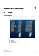
Properties of the TS Adapter IE Basic 1.1 1 Functions Hardware Requirements To use the functions of the TS Adapter IE Basic , you must operate it together with a TS module. The TS module is placed sideways on the TS Adapter IE Basic and forms the physical interface to the telephone or mobile network.
Properties of the TS Adapter IE Basic 1.1 Functions Depending on the application involved, you may need a special TS module. Basic unit Plug-in TS modules Article number TS Adapter IE Basic TS Module Modem 6ES7972-0MM00-0XA0 TS Module ISDN 6ES7972-0MD00-0XA0 TS Module RS232 6ES7972-0MS00-0XA0 TS Module GSM 6GK7972-0MG00-0XA0 You can find additional information about the TS modules and the modular design in the Modular TS Adapter manual.
Properties of the TS Adapter IE Basic 1.1 Functions The following diagram illustrates the various functions of the TS Adapter IE Basic.
Properties of the TS Adapter IE Basic 1.2 Features 1.2 Features Characteristics of the TS Adapter IE Basic ● Connection to PG/PC and automation system via Industrial Ethernet ● Support for routing ● Support for the function blocks AS_MAIL, TM_MAIL and TMAIL_C, depending on the CPU type used ● Integrated DIN rail fastener 1.3 Connection Types Connection types of the TS Adapter IE Basic The following diagrams show the connection types possible with the TS Adapter IE Basic.
Properties of the TS Adapter IE Basic 1.3 Connection Types Connection to the telephone network To have a direct connection to the telephone network, you must operate the TS Adapter IE Basic together with one of the following TS modules: ● TS Module Modem ● TS Module ISDN Figure 1-4 Direct connection to the telephone network You can find additional information about the TS modules in the Modular TS Adapter manual.
Properties of the TS Adapter IE Basic 1.4 Mounting methods Connection to the telephone network through an external modem For the connection to an external modem, you must operate the TS Adapter IE Basic together with the TS Modul RS232: ● TS Module RS232 Figure 1-6 Connection to an external modem You can find additional information about the TS modules in the Modular TS Adapter manual. 1.
Properties of the TS Adapter IE Basic 1.5 Product Package and Spare Parts 1.
Properties of the TS Adapter IE Basic 1.
Requirements for operation 2.1 2 Software Requirements Overview To work with the TS Adapter IE Basic , you need a PG/PC with an MS Windows operating system and the software (device drivers) for the TS Adapter IE Basic. The list of the supported operating systems is included in the latest Readme file on the TS Adapter IE Basic software. For first-time configuration of IP addresses over a direct connection you will alternatively need: ● SIMATIC TIA Portal V11.0 or higher ● SIMATIC TeleService V6.
Requirements for operation 2.
3 Connecting 3.
Connecting 3.2 Power Supply 3.2 Power Supply Power supply The TS Adapter IE Basic is supplied and grounded with the help of the delivered power through the power socket to its top side with DC 24 V. The following image shows the TS Adapter IE Basic in the view from above: ① Power socket for the 24 V DC Power Supply DANGER Only safely isolated 24 V DC low voltage may be used for the power supply.
Connecting 3.2 Power Supply Wiring the connectors To change the voltage, proceed as follows: 1. If you want to use ferrules, isolate the wires to 10 mm. Cap the crimp ferrules with the lines. Strip about 8 to 10 mm off the wires. 2. Place the cores on (①). 3. Screw the ends of the cores with the voltage, tightening torque: 0.6 to 0.8 Nm (②). L+ 24 V DC M Ground Ground connection Figure 3-2 Change the voltage Plug on voltage place the wired voltage ① until it locks into the power socket.
Connecting 3.3 Ethernet Port 3.3 Ethernet Port The TS Adapter IE Basic has an Ethernet port with an 8-pin RJ45 socket. To that socket you connect an Industrial Ethernet cable. The cable is not included in the product package of the TS Adapter IE Basic. You can use a standard Ethernet cable or a crossover cable with crossed wires. The TS Adapter IE Basic supports automatic switching between the two cable variants. The cable must be fitted with 8-pin RJ45 connectors conforming to ISO/IEC 8877:1992.
Connecting 3.3 Ethernet Port Insert system plug As an alternative to an Ethernet cable with an IEEE 802.3 plug, you can also use an/the Ethernet cable with the system plug (Industrial Ethernet 6GK1901-1BB10-2AA0 (1800) or 6GK1901-1BB30-0AA0 (1450)). This plug must be assembled with the supplied support collar (A5E02284492) as strain relief: 1. First attach the support collars ① to the Ethernet port of the TS Adapter IE Basic. The support collar locks in. 2.
Connecting 3.3 Ethernet Port Remove system plug 1. Press the position on the system plug marked with ③ in order to release the lock. 2. Pull out the system plug (④). The support collar can remain on the TS Adapter IE Basic . With a support collar you can also use a cable with a RJ45 plug according to ISO/IEC 8877:1992. Note If you confuse the Ethernet connector with the ISDN connector for the TS Module ISDN, the TS Adapter IE Basic will malfunction.
Connecting 3.
Connecting 3.4 Module interface TS Adapter IE Basic in the direct connection in a networked system In a networked system, connect the TS Adapter IE Basic over Ethernet to a switch to which a PG/PC and automation components are connected for example: Figure 3-7 3.4 Direct connection in a networked system Module interface On the left side of the TS Adapter IE Basic you can find the module interface. Depending on the application, you can plug the respective TS module into this interface.
Commissioning 4.1 4 Safety Instructions Qualified personnel The device may only be serviced by qualified personnel. Qualified personnel under the terms of the safety instructions contained in this manual is defined as persons who are authorized to commission, ground and label devices, systems and circuits in accordance with established safety practices and standards.
Commissioning 4.2 Overview 4.2 Overview Commissioning options The TS Adapter IE Basic has a Web interface that can be used to set the parameters of the TS Adapter IE Basic. In the delivery state and after a parameter reset, the IP parameters of the TS Adapter IE Basic are set so that remote maintenance and e-mail are not possible. The following table shows an overview of the various options for commissioning the TS Adapter IE Basic into operation: Step Commissioning ... ...
Commissioning 4.3 Setting the PG/PC Interface 4.3 Setting the PG/PC Interface Procedure Note This chapter is only relevant for classic applications. Users of the TIA Portal do not use the PG/PC interface. During installation of the software you are prompted to set the PG/PC interface. 1. Open the "Set PG/PC interface" dialog box to verify it. – If "TS Adapter IE" interface is included in the selection list, go to step 5. – If "TS Adapter IE" interface is missing from the list, continue with step 2. 2.
Commissioning 4.4 Connecting the TS Adapter IE Basic 4.4 Connecting the TS Adapter IE Basic Note If you connect the Ethernet plug to the ISDN slot of the TS Module ISDN, this will lead to a malfunction of the TS Adapter IE Basic. Only connect the Ethernet cable to the Ethernet port of the TS Adapter IE Basic. Connecting to PG/PC The direct connection of the TS Adapter IE Basic to PG/ PC is only required for configuration of the TS Adapter IE Basic. 1.
Commissioning 4.5 Setting IP Parameters of TS Adapter IE Basic for the First Time 4.5 Setting IP Parameters of TS Adapter IE Basic for the First Time In the delivery state and after resetting the parameters, the TS Adapter IE Basic will not have an IP address (0.0.0.0). To be able to work with the TS Adapter IE Basic, you must first set its IP parameters.
Commissioning 4.5 Setting IP Parameters of TS Adapter IE Basic for the First Time Result If you now again select "Update accessible participants", TS Adapter IE Basic and its IP address is shown. 4.5.2 Setting IP Parameters by Direct Connection with TeleService Requirement ● You have a free Ethernet port on your PG/PC. ● You have installed TeleService from the "SIMATIC TeleService Edition" DVD in accordance with the installation instructions in the TeleService manual. Procedure 1.
Commissioning 4.6 Establishing a Remote Connection to the TS Adapter IE Basic 4.5.3 Setting IP Parameters by Direct Connection with the SIMATIC Manager Requirement You have a free Ethernet port on your PG/PC and the SIMATIC Manager is installed. Procedure 1. Connect the Ethernet port of your PG/PC to the Ethernet port of the TS Adapter IE Basic. 2. Connect the TS Adapter IE Basic to the power supply. 3.
Commissioning 4.
Commissioning 4.6 Establishing a Remote Connection to the TS Adapter IE Basic 4.6.1 Establishing a remote connection to the TS Adapter IE Basic with the TIA Portal Requirements ● You have connected and commissioned a modem or ISDN-TA on your PG/PC (with installed TIA Portal software). ● You have connected the TS Adapter IE Basic to your power supply. ● You have connected the TS Adapter IE Basic to the telephone network via a telephone cable.
Commissioning 4.6 Establishing a Remote Connection to the TS Adapter IE Basic 4.6.2 Establishing a Remote Connection to the TS Adapter IE Basic via TeleService Requirement ● You have connected and put into operation a modem or ISDN TA on your PG/PC. ● You have installed TeleService from the "SIMATIC TeleService Edition" DVD in accordance with the installation instructions in the TeleService manual. Procedure 1. Connect the TS Adapter IE Basic via a phone cable to the phone network. 2.
Commissioning 4.6 Establishing a Remote Connection to the TS Adapter IE Basic 4.6.3 Establishing a Remote Connection to the TS Adapter IE Basic via a Dial-up Connection Requirement You have connected and put into an operation a modem or ISDN TA on your PG/PC. Procedure (Windows 7®) 1. Connect the TS Adapter IE Basic via a phone cable to the phone network. 2. Connect the TS Adapter IE Basic to the power supply. 3. Commission your local modem on the PC as set out in the modem manual.
Commissioning 4.6 Establishing a Remote Connection to the TS Adapter IE Basic Checking status of remote connection 1. Click "Start" > "Control Panel" > "Network Connections". 2. Right-click on your connection to open its shortcut menu. 3. Select "Status" in the shortcut menu. In the "General" tab of the Status dialog box, you can see if the connection has been made. Result Now you can open the Web interface of the TS Adapter IE Basic with a browser.
Commissioning 4.7 Parameter assignment of TS Adapter IE - Overview 4.7 Parameter assignment of TS Adapter IE - Overview Overview You can use the Web interface of the TS Adapter IE Basic to: ● Parameterize the TS Adapter IE Basic. ● Restore the standard setting of the TS Adapter IE Basic. ● Export the parameter set of the TS Adapter IE Basic. ● Import the parameter set of the TS Adapter IE Basic.
Commissioning 4.
Commissioning 4.8 Open Web interface 4.8.1 Open Web interface in direct connection with the TIA Portal Requirements ● You have a LAN connection from your PG/PC (with installed TIA Portal software) to the TS Adapter IE Basic and have connected the TS Adapter IE Basic to your power supply. ● The IP address of your PG/PC's interface card is in the same subnet as the IP address you assigned to the TS Adapter IE Basic. ● You have already set the IP parameters of the TS Adapter IE Basic. Procedure 1.
Commissioning 4.8 Open Web interface 4.8.2 Open Web interface via a remote connection with the TIA Portal Note Through a remote connection, you can also reach the Web interface of the TS Adapter IE Basic if you have not yet assigned an IP address to the TS Adapter IE Basic. Requirements ● You have connected and commissioned a modem or ISDN-TA on your PG/PC (with installed TIA Portal software). ● You have connected the TS Adapter IE Basic to your power supply.
Commissioning 4.8 Open Web interface 4.8.3 Open Web interface in direct connection with TeleService Requirements ● You have installed TeleService from the "SIMATIC TeleService Edition" DVD in accordance with the installation instructions in the TeleService manual. ● You have already set the IP parameters of the TS Adapter IE Basic. ● The IP address of your PG/PC's interface card is in the same subnet as the IP address you assigned to the TS Adapter IE Basic. Procedure 1.
Commissioning 4.8 Open Web interface 4.8.4 Open Web interface in direct connection with a browser Requirement You have already set the IP parameters of the TS Adapter IE Basic. Note The IP address of the PC interface card and the IP address of the TS Adapter IE Basic must belong to the same subnet. Procedure 1. Connect the TS Adapter IE Basic via an Ethernet cable to your PG/PC. 2. Connect the TS Adapter IE Basic to the power supply. 3. Launch a browser. 4.
Commissioning 4.8 Open Web interface 4.8.5 Open Web interface using a remote connection with TeleService Note Through a remote connection, you can also reach the Web interface of the TS Adapter IE Basic if you have not yet assigned an IP address. Procedure 1. Connect the TS Adapter IE Basic via a phone cable to the phone network. 2. Connect the TS Adapter IE Basic to the power supply. 3. Establish a modem connection from your PG/PC to the TS Adapter IE Basic with TeleService.
Commissioning 4.8 Open Web interface 4.8.6 Open Web interface using a remote connection with a browser Note Through a remote connection, you can also reach the Web interface of the TS Adapter IE Basic if you have not yet assigned an IP address. Procedure 1. Connect the TS Adapter IE Basic via a phone cable to the phone network. 2. Connect the TS Adapter IE Basic to the power supply. 3. Establish a remote connection from your PC to the TS Adapter IE Basic. 4.
Commissioning 4.9 Setting Remote Maintenance Parameters 4.9 Setting Remote Maintenance Parameters Requirements ● You have correctly set the IP parameters for the network and for the modem. ● The Web interface of the TS Adapter IE Basic is open. Remote maintenance parameters The TS Adapter IE Basic is configured such that it is possible to establish a remote connection in most cases. If you are unable to establish a remote connection, refer to the section "Error diagnostics (Page 55)".
Commissioning 4.10 Setting the E-mail Parameters 4.10 Setting the E-mail Parameters Requirement ● The Web interface of the TS Adapter IE Basic is open. Sending e-mail The TS Adapter IE Basic routes IP telegrams between its Ethernet port and the remote connection to a dial-up server, such as to an Internet Service Provider (ISP).
Commissioning 4.11 Sending an E-mail from a SIMATIC CPU 4.11 Sending an E-mail from a SIMATIC CPU Function block for sending e-mail To send an e-mail from a SIMATIC CPU, you can use the AS_MAIL, TM_MAIL or TMAIL_C function blocks, depending on the CPU type. You can find additional information about the AS_MAIL, TM_MAIL and TMAIL_C function blocks in the online help for the respective block.
Commissioning 4.13 Resetting the Configuration with P RES button 4.13 Resetting the Configuration with P RES button It may be necessary to reset the configuration if the adapter parameters on a remote system have been altered such that you are no longer able to access the TS Adapter IE Basic via the modem connection. P RES button The TS Adapter IE Basic has a Reset button (P RES) with which you can reset the adapter to its default configuration.
Commissioning 4.13 Resetting the Configuration with P RES button Procedure NOTICE Parameter settings will be lost If you reset the configuration of the TS Adapter IE Basic, all the parameter settings you made will be lost and the preset "admin" password is reactivated. 1. Use a sharp implement, such as a paper clip, to press the P RES button and hold it down for about 2 seconds. The TS Adapter IE Basic acknowledges the P RES reset by flashing the the yellow LED Run three times.
Commissioning 4.
Firmware update 5 Note Updating the firmware Check regularly if firmware updates are available. Always install the latest firmware on the TS Adapter IE Basic to receive the latest security updates and feature enhancements. Note that a firmware update can only be performed by a user with administrator privileges. Procedure To update the firmware: 1. You can find the latest firmware for the TS Adapter IE Basic on the Internet (http://support.automation.siemens.com/WW/view/de/48204213/dl). 2.
Firmware update The configuration of the TS Adapter IE Basic is retained during the firmware update. Note If the connection to the TS Adapter IE Basic is disrupted during the download procedure or installation, or if you switch off the power supply to the TS Adapter IE Basic, the firmware update will fail. The TS Adapter IE Basic then works again with the old firmware state. Ensure that neither the download nor the subsequent installation procedure is interrupted.
6 Error diagnostics 6.1 Error Diagnostics Based on LEDs With the help of the LED displays, simple disruptions can be diagnosed and repaired independently. Table 6- 1 LED display for operating state of the TS Adapter IE Basic LED Cause RUN (green/yellow) ERROR (red) MAINT (yellow) Illuminated green – – Off Off Off – Lit – The TS Adapter IE Basic is ready for operation. Measures/remedy – No power supply Establish the power supply. No TS module inserted Insert a TS module.
Error diagnostics 6.2 Logon to the Web interface fails Table 6- 2 LED displays for the Ethernet interface LED Cause Link (green) RX/TX (yellow) Off Off Lit – Lit Flashes Remedy No Ethernet cable inserted Insert the Ethernet cable. No connection to the receiver Check the receiver. Ethernet cable inserted Functional connection – Data is transmitted through the Ethernet interface. – The LEDs link and RX/TX are located behind the lower front panel of the TS Adapter IE Basic. – any 6.
Error diagnostics 6.3 Logon to the Web interface is denied 6.3 Logon to the Web interface is denied Error message "The TS Adapter IE Basic is not allowing any further logon at present. Try again later." Possible cause A user is already signed on to the TS Adapter IE Basic. The TS Adapter IE Basic is occupied through this. No further logon is possible. Remedy 1. Take one of the following actions: – Click "Logout" to close a running session.
Error diagnostics 6.4 Malfunctions in remote maintenance 6.4 Malfunctions in remote maintenance 6.4.1 The partner is not answering Error message on connecting "Partner not answering" Remedy 1. Check the phone cables and the power connection of the TS Adapter IE Basic. 2. Check the LED ERROR on the TS Adapter IE Basic. If the LED is lit, read the section "Error Diagnostics Based on LEDs (Page 55)". 3.
Error diagnostics 6.4 Malfunctions in remote maintenance 7. Check the response of the modems on the TS Adapter IE Basic to the initialization strings. You can also view the response of the modems in the "Information > Status" tab of the Web interface. If ERROR or TIMEOUT is displayed as the status, the modem does not understand the initialization string. Correct the initialization string. 8.
Error diagnostics 6.4 Malfunctions in remote maintenance 6.4.3 The callback fails Diagnostics The call to the TS Adapter IE Basic is successful, but the callback fails. Remedy 1. Check the callback procedure. If you have entered a callback number for the selected user in the "Security > User Management" tab, the TS Adapter IE Basic uses that number for the callback. If you have not entered anything for the callback number parameter, you can specify any callback number when making a connection on the PC.
Error diagnostics 6.5 Malfunctions when establishing an outgoing call 6.5 Malfunctions when establishing an outgoing call 6.5.1 Check connection establishment Procedure for checking the connection establishment 1. In the "Parameters > Outgoing Calls" tab, set the "Connection establishment" parameter to "never" and click "Save Setting". Any active connection establishment is aborted. 2.
Error diagnostics 6.5 Malfunctions when establishing an outgoing call 6.5.3 The connection establishment fails Diagnostics The modem connection is made, but the remote connection establishment fails. The DCD LED on the TS module or modem lights up and goes dark again (CONNECTED LED with TS Module GSM). Remedy 1. Check the user name and password in the "Parameters > Outgoing Calls" tab. 2. If you are using an ISDN connection, make sure the B-channel settings of the two ISDN TAs match. 3.
Error diagnostics 6.6 Not possible to send e-mail 6.6 Not possible to send e-mail Diagnostics An outbound modem connection is active, but e-mail cannot be sent. In the "Information > Status" tab of the Web interface, you can check if an outbound connection is active. Remedy 1. Check the LED LINK on the TS Adapter IE Basic. If it is not lit, there is no connection to another device over Ethernet. You can see the status of the Ethernet connection in the "Information > Status" tab of the Web interface. 2.
Error diagnostics 6.7 Error diagnostics - Ethernet 6.7 Error diagnostics - Ethernet 6.7.1 You do not know the IP address of the TS Adapter IE Basic. Remedy ● By direct connection with TeleService Proceed as described in the "Setting IP Parameters by Direct Connection with TeleService (Page 32)" section. Follow the instructions in steps 1 through 7. ● Direct connection with TIA Portal Proceed as described in the "Setting IP parameters by direct connection with the TIA Portal (Page 31)" section.
7 Technical data 7.1 General Specifications What are general specifications? The general specifications include the following: ● The standards and test values the TS Adapter IE Basic includes and meets. ● Test criteria to which the TS Adapter IE Basic was tested. TS Adapter IE Basic Article number TS Adapter IE Basic 6ES7 972-0EB00-0XA0 Dimensions (H x W x D) 100 x 30 x 75 mm Weight ca. 100 g Interfaces To SIMATIC S7 / C7 To the PG/PC Ethernet Ethernet Power supply DC 24 V (SELV/LPS) (DC 19.
Technical data 7.1 General Specifications Horizontal and vertical installation Comply with the general installation guidelines for SIMATIC. Cabinet installation is stipulated. You can install the TS Adapter IE Basic vertically or horizontally.
Technical data 7.2 Electromagnetic Compatibility 7.2 Electromagnetic Compatibility Definition of "EMC" Electromagnetic Compatibility (EMC) defines the capability of electrical equipment to operation satisfactorily in its electromagnetic environment without influencing this environment. WARNING Injury to persons or damage to property may occur.
Technical data 7.2 Electromagnetic Compatibility Sinusoidal interference The table below shows the EMC characteristics of the TS Adapter IE Basic with regard to sinusoidal disturbance variables. Table 7- 2 Sinusoidal interference Sinusoidal interference Test values Equivalent to severity HF irradiation (electromagnetic fields) according to IEC 61000-4-3 10 V/m with 80% amplitude modulation of 1 kHz in the range from 80 MHz to 1000 MHz and 1.4 GHz to 2 GHz.
Technical data 7.3 Transportation and Storage Conditions 7.3 Transportation and Storage Conditions Transportation and storage of modules With regard to transportation and storage conditions, the TS Adapter IE Basic surpasses the requirements specified in IEC 61131-2. The following conditions apply to TS Adapter IE Basic that are transported and stored in the original packaging. Climatic conditions compliant with IEC 60721-3-3, class 3K7 for storage and IEC 60721-3-2, class 2K4 for transportation.
Technical data 7.4 Mechanical and Climatic Ambient Conditions for Operation of the TS Adapter IE Basic 7.4 Mechanical and Climatic Ambient Conditions for Operation of the TS Adapter IE Basic Operating conditions The TS Adapter IE Basic is designed for stationary use in weather-proof locations.
Technical data 7.4 Mechanical and Climatic Ambient Conditions for Operation of the TS Adapter IE Basic Testing of mechanical environmental conditions The table below provides information on the type and scope of testing of mechanical ambient conditions. Table 7- 5 Testing of mechanical environmental conditions Test of ... Test standard Comments Vibration Vibration test to IEC 60068-2-6 (sine wave) Vibration type: Frequency sweeps at a rate of change of 1 octave per minute.
Technical data 7.5 Information on protection class and degree of protection 7.5 Information on protection class and degree of protection Protection class The modular TS Adapter conforms to protection class III in accordance with EN 61140:2002 (VDE 0140-1). Protection against foreign bodies and water The TS Adapter IE Basic fulfills the protection type IP20 according to IEC 60529. The TS Adapter IE Basic is protected against contact with standard probes.
Technical data 7.6 Standards, Approvals, Certificates, Guidelines, Labels and Declarations EMC Directive SIMATIC products are designed for industrial applications.
Technical data 7.6 Standards, Approvals, Certificates, Guidelines, Labels and Declarations cULus approval, Hazardous Location cULus Listed 7RA9 INT. CONT. EQ. FOR HAZ. LOC. Underwriters Laboratories Inc. to ● UL 508 (Industrial Control Equipment) ● CSA C22.2 no. 142 (Process Control Equipment) ● ISA-12-12-01 (Hazardous Location) ● CSA-213 (Hazardous Location) APPROVED for Use in ● Cl. 1, Div. 2, GP. A, B, C, D T4A ● Cl. 1, Zone 2, GP.
Technical data 7.6 Standards, Approvals, Certificates, Guidelines, Labels and Declarations FM approval Factory Mutual Approval Standard Class Number 3611, Class I, Division 2, Group A, B, C, D, T4A. Class I, Zone 2, Group II C, T4. WARNING Injury to persons or damage to property may occur. In hazardous areas, personal injury or property damage can result if you create or break an electrical circuit during operation of a TS Adapter IE Basic (for example, by means of plug-in connections, fuses, switches).
Technical data 7.
Service & Support A Unmatched complete service for the entire life cycle For machine manufacturers, solution providers and plant operators: The service offering from Siemens Industry Automation and Drive Technologies includes comprehensive services for a wide range of different users in all sectors of the manufacturing and process industry.
Service & Support Online Support The comprehensive online information platform supports you in all aspects of our Service & Support at any time and from any location in the world. You can find Online Support at the following address on the Internet (http://www.siemens.com/automation/service&support).
Service & Support Optimization During the service life of machines and plants, there is often a great potential for increasing productivity or reducing costs. To help you achieve this potential, we are offering a complete range of optimization services. Modernization You can also rely on our support when it comes to modernization – with comprehensive services from the planning phase all the way to commissioning.
Service & Support TS Adapter IE Basic 80 Manual, 08/2014, A5E02615140-03
Glossary AES Advanced Encryption Standard is a symmetrical cryptographic system that provides a very high level of security. Automation system An automation system is a programmable logic controller consisting of at least one CPU, various input and output modules, and operator control and monitoring devices. CHAP Challenge Handshake Authentication Protocol (RFC 1994) Access is checked by encrypting and decrypting a random number. Configuration Configuration refers to the setting of a module's behavior.
Glossary DHCP Dynamic Host Configuration Protocol: enables assignment of the network configuration to clients by a server (RFC 2131). Diagnostics functions The diagnostics functions cover the entire system diagnostics and include the recognition, interpretation and reporting of errors within the automation system. DNS Domain Name System: service for responding to requests for name resolution.
Glossary IP Internet Protocol: network protocol that is used widely in computer networks and is the basis for the Internet. LAN Local Area Network: computer network whose area is limited to 500 m without additional measures and is generally used in small companies. Lifetime Service life / usability of an IPv6 address. The following cases are distinguished: ● Preferred lifetime > 0: The address is available for new connections.
Glossary Service life See Lifetime SLAAC Stateless Address Autoconfiguration: Stateless address autoconfiguration in IPv6 mode (RFC 4862). SMTP Simple Mail Transfer Protocol: protocol of the Internet protocol family for exchanging e-mails in computer networks. SMTPS Simple Mail Transfer Protocol Secure: Protocol for e-mail exchange in computer networks including SSL encryption. Software Software refers to the entirety of all programs that are used on a computing system.
Index A Access to automation component fails, 60 Ambient conditions, 70 Approvals, 72 Assigning parameters, 17 Automation system Connect adapter, 30 Establish remote connection Via remote connection, 33, 37 via TeleService, 33, 36 via the TIA Portal, 35 Ethernet cable, 22 Ethernet port, 22 Pin assignment, 24 Explosion Protection Directive, 73 F C Callback fails, 60 Callback number, 60 CE mark, 72 Check connection establishment, 61 Climatic ambient conditions, 71 Configuration First-time, 17, 25 reset, 49,
Index O Open Web interface via Ethernet with browser, 44 via Ethernet with TeleService, 43 via Ethernet with TIA Portal, 41 via remote connection with browser, 46 via remote connection with TeleService, 45 Operating conditions, 70 P P RES (reset) button, 50 Partner not answering, 58 PC Connect the TS Adapter IE Basic, 30 PG/PC interface set, 29 Pin assignment Ethernet port, 24 Product package, 15 Specifications, 65 Storage conditions, 69 T Transportation conditions, 69 TS Adapter IE Basic Connection to