
Specifications


Connecting
5.5 RS232 Port
TS Adapter IE
34 Manual, 06/2008, A5E00977705-02
5.5 RS232 Port
The TS Adapter IE has a COM port configured as a RS232C interface, which is used solely
for connecting external modems.
You can operate the following devices from the COM port:
● Standard modems
● ISDN terminal adapters
● GSM wireless modems with an RS232 port
NOTICE
The specifications relating to interference immunity and interference emission apply only
when using devices, lines and connectors conforming to industrial requirements in
accordance with EN 61000-6-4:2001 and EN 61000-6-2:2001.
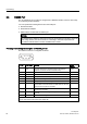
Pin assignment and signal description of RS232C port X2
The RS232 connector is configured as follows:
Pin no. Short name Meaning Input/
Output
1 DCD Received signal level - the DCE signals to the DTE the
reception of a carrier and the connection setup.
Input
2 RXD Received data - from DCE
1
to DTE
2
Input
3 TXD Transmitted data - from DTE to DCE Output
4 DTR Ready to send - the DTE signals this to the DCE. Output
5 GND Internal reference ground
6 DSR Ready to operate - the DCE signals this to the DTE. Input
7 RTS Switch on transmission unit - the DTE requests the DCE to
transmit data on the data cable. The DTE waits for the CTS
(ready-to-send) signal from the DCE.
Output
8 CTS Ready to send - the DCE is able to transfer the data
incoming from the DTE.
Input
9 RI Incoming call - the DCE signals reception of a call signal to
the DTE.
Input
Shield On connector housing -
1
DCE = Data Communication Equipment (modem or ISDN-TA)
2
DTE = Data Terminal Equipment (TS Adapter IE)