
Technical data
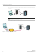


Table of contents
TS Adapter II
6 Manual, 06/2008, A5E00272728-03
6.3 Use on networked system........................................................................................................... 42
6.3.1 Connection to networked S7 systems.........................................................................................
42
6.3.2 Connection in the ring .................................................................................................................
42
7 Firmware update......................................................................................................................................
43
8 Error diagnostics......................................................................................................................................
45
A Appendix..................................................................................................................................................
47
A.1 Standards, Approvals, Certificates, Guidelines, Labels, and Declarations.................................
47
A.2 Customer Information for ACTA..................................................................................................
52
A.3 General technical specifications .................................................................................................
53
A.3.1 Electromagnetic compatibility .....................................................................................................
55
A.3.2 Shipping and storage conditions.................................................................................................
57
A.3.3 Mechanical and climatic environmental conditions for operation of the TS Adapter II ...............
57
A.3.4 Specification of Insulation Testing, Protection Class and Degree of Protection /Test
Voltage ........................................................................................................................................
59
Index........................................................................................................................................................
61
Tables
Table 1-1 Bus profiles and baud rates ..........................................................................................................
9
Table A-1 Pulse-shaped Interference..........................................................................................................
55
Table A-2 Sinusoidal Interference ...............................................................................................................
56
Table A-3 Shipping and storage conditions for modules.............................................................................
57
Table A-4 Mechanical environmental conditions .........................................................................................
58
Table A-5 Test for mechanical environmental conditions............................................................................
58
Table A-6 Climatic environmental conditions ..............................................................................................
59
Figures
Figure 1-1 TS Adapter II with direct connection .............................................................................................
8
Figure 1-2 TS Adapter II with modem connection..........................................................................................
8
Figure 3-1 Rear panel of the TS Adapter II ..................................................................................................
14
Figure 3-2 Slide for installing the TS Adapter II on a DIN rail ......................................................................
16
Figure 3-3 Installing TS Adapter II................................................................................................................
16
Figure 3-4 Minimum clearance .....................................................................................................................
17
Figure 4-1 TS Adapter II-Modem..................................................................................................................
19
Figure 4-2 TS Adapter II-ISDN .....................................................................................................................
20
Figure 4-3 LEDs of the TS Adapter II ...........................................................................................................
21
Figure 4-4 MPI cable, 0.8 m with 9-pin sub D connectors............................................................................
25
Figure 4-5 MPI cable (0.8 m)........................................................................................................................
25
Figure 5-1 Front view with reset button ........................................................................................................
39
Figure 6-1 Connection to a stand-alone system...........................................................................................
41