
Technical data


TS Adapter II on the MPI/DP/PPI network
6.3 Use on networked system
TS Adapter II
42 Manual, 06/2008, A5E00272728-03
6.3 Use on networked system
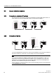
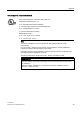
6.3.1 Connection to networked S7 systems
The following figure shows the connection to networked S7 systems (MPI network with 2 or
more nodes). You use the supplied MPI cable to connect the TS Adapter II.
6[ 6\ 6[
76$GDSWHU,,
6XSSOLHG03,FDEOH 352),%86FDEOH 352),%86FDEOH
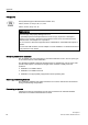
6.3.2 Connection in the ring
6[ 6\ 6]
76$GDSWHU,,
352),%86FDEOH352),%86FDEOH 352),%86FDEOH
H[WHUQDO9
VXSSO\
You use a PROFIBUS DP connector to connect the TS Adapter II in the ring (not included in
the scope of delivery). In this case, you must supply 24 V to the TS Adapter II.
Note
If you want to install the TS Adapter II together with other S7-300 modules in a rack, you
must take into account the fact that the TS Adapter II has no backplane bus. There must
therefore be no S7-300 modules that communicate with the CPU over the backplane bus
(SM, FM or CP) installed to the right of the TS Adapter II.
If the TS Adapter II is the last module in the ring, the terminating resistors must be activated
on the PROFIBUS DP connector.