
Technical data
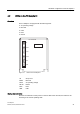
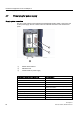

Hardware configuration of the TS Adapter II
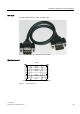
4.6 RS232 interface
TS Adapter II
Manual, 06/2008, A5E00272728-03
27
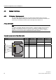
4.6 RS232 interface
The TS Adapter II has a COM interface configured as an RS232C interface, which is used
solely for connecting external modems.
Standard modems, ISDN terminal adapters, or GSM radio modems can be connected to and
operated on the COM interface.
Note
The firmware detects the insertion of an external modem and switches automatically from
internal to external modem operation.
Simultaneous internal and external modem operation is not possible.
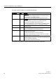
Connector assignment
The RS232 plug connector has the following pinout:
Signal description
Pin. No. Short
description
Meaning Input/
output
1 DCD Data carrier detect - the DCE signals to the DTE the reception
of a carrier or the connection setup
Input
2 RXD Receive data - from DCE
1
to DTE
2
Input
3 TXD Transmit data - from DTE to DCE Output
4 DTR Data terminal ready - the DTE signals this to the DCE Output
5 GND Internal reference ground
6 DSR Data set ready - the DCE signals this to the DTE Input
7 RTS Request to send - the DTE requests the DCE to transmit data
on the data cable. The DTE waits for the CTS (clear to send)
signal from the DCE
Output
8 CTS Clear to send - the DCE is able to transmit the data incoming
from the DTE
Input
9 RI Ring indicator - the DCE signals reception of a call signal to the
DTE
Input
Shield On connector casing -
1
DCE = Data communication equipment
2
DTE = Data terminal equipment