
Technical data
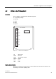
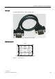

Hardware configuration of the TS Adapter II
4.4 MPI/DP interface
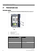
TS Adapter II
24 Manual, 06/2008, A5E00272728-03
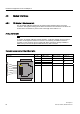
4.4 MPI/DP interface
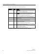
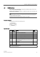
Connector assignment
The MPI/DP socket has the following pinout:
Signal description
Pin. No. Short
description
Meaning Input/
output
1 NC Not connected -
2 M24V For 0 V line of the 24 V supply; supplies the
adapter electronics via a DC/DC converter (PC
potential area)
Input
3 LTG_B Data line B Input/output
4 RTS_AS RTS_AS, control signal for receive data stream.
The signal is "1" when the directly connected AS
is sending
Input
5 M5V Reference potential of MPI/DP interface for the
RTS_AS and RTS_PG signals
Input
6 P5V For supplying power to terminating resistors Output
7 P24V For +24V line of the 24 V supply; supplies the
adapter electronics via a DC/DC converter (PC
potential area)
Input
8 LTG_A Data line A Input/output
9 RTS_PG RTS output signal of the adapter. The signal is
"1" when the adapter is sending.
The signal is not contained in the MPI cable.
Output
Shield On connector casing* -
* The shield is interconnected with the USB socket via the adapter electronic module.
WARNING
Use the MPI cable described below and supplied with your TS Adapter II only for
transmission rates up to 1500 kbps. If you want to operate the adapter on systems with
higher transmission rates, use a PROFIBUS cable. In this case, you must supply power to
the TS Adapter II with an external 24 V supply.