
Operating instructions

4
AUI connection (ELM)
An AUI port to IEEE 802.3 enables ELM
equipment to be connected to an Ethernet
segment via a bus coupler. The data and CD
lines of the AUI port are DC-decoupled from
the supply voltages. The voltage (+ 12 V DC)
to supply a bus coupler has the earth of the
supply voltage as a reference potential.
Note: When connecting the ELM to a
SINEC bus coupler with 2 interfaces (level 4
of issue or less), use only the left-hand
interface of the coupler.
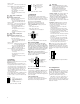
Fig. 5: Pin configuration of 5-pin terminal
block
+24 V
+24 V *
Fault
L1+
L2+
M
F1
F2
GND
Collision in CI-A
Transmit DO-A
GND
Receive DI-A
GND
not used
GND
Pin 1
Pin 2
Pin 3
Pin 4
Pin 5
Pin 6
Pin 7
Pin 8
Pin 9
Pin 10
Pin 11
Pin 12
Pin 13
Pin 14
Pin 15
Collision in CI-B
Transmit DO-B
GND
Receive DI-B
Voltage +12 V / 0,5 A
GND
not used
Fig. 4: Pin configuration of AUI interface
Pin 6 RD-
Pin 7 n.c.
Pin 8 n.c.
Pin 9 TD-
RD+ Pin 1
n.c. Pin 2
n.c. Pin 3
n.c. Pin 4
TD+ Pin 5
Fig. 3: Pin configuration of an ITP interface
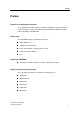
1.5 CONTROLS
6-pin DIP switch
Using the 6-pin DIP switch on the top of the
OLM/ELM housing
– the message about the link statuses can
be suppressed by the indicator contact on
a port-by-port basis. Using switches LA1
to LA5 (LA1 to LA3 on the ELM), the mes-
sage about the link status of ports 1 to 5
(1 to 3 on ELM) is suppressed. State on
delivery: switch position 1 (on), i.e. messa-
ge not suppressed.
- port 5 can be switched to redundant mode
(on the OLM). State on delivery: switch
position 0 (off), i.e. port 5 in normal mode.
Fig. 1: 6-pin DIP switch on OLM
LA1
R5
Off On
LA5
LA3
LA2
LA4
Port 1
Port 5
Port 5
Port 3
Port 2
Port 4
about link status
Suppress message
via indicator contact
Redundant mode
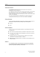
Fig. 2: 6-pin DIP switch on ELM
LA1
Off On
LA3
LA2
Port 1
Port 3
Port 2
about link status
Suppress message
via indicator contact
not configured
F/O connection (OLM)
2 optical ports to 10BASE-FL (BFOC/2.5 (ST)
sockets) enable OLM equipment to be cas-
caded as well as redundant rings to be con-
structed using F/Os and terminal equipment
to be connected.
5-pin terminal block
The supply voltage and the indicator
contact are connected via a 5-pin terminal
block with screw locking mechanism.
1.6 INTERFACES
ITP connection
Three 9-pin sub-D sockets enable three
independent ITP segments to be connected.
The socket casings are electrically connec-
ted to the front panel and thus connected to
the housing of the OLM/ELM.
Mechanical locking is by means of a
UNC 4-40 screw locking mechanism.
– Pin configuration of the 9-pin sub-D
socket:
– TD+: pin 5, TD-: pin 9
– RD+: pin 1, RD-: pin 6
– remaining pins: not configured.
– flashes 2 times
per period: port has auto partitioned
– lit not: OLM not receiving any link test
pulses from F/O segment,
– the assigned F/O port is not
connected,
– the equipment connected is
switched off,
– the F/O receiving fibre is inter-
rupted
LS5 – Link status of F/O port 5
(green LED)
Normal mode switched on
– lit: OLM receiving link test pulses
from F/O segment,
– the connected redundant F/O
segment is working properly
– flashes 2 times
per period: port has auto partitioned
– lit not: OLM not receiving any link test
pulses from F/O segment,
– the assigned F/O port is not
connected,
– the equipment connected is
switched off,
– the F/O receiving fibre is inter-
rupted
LS5 – Link status of F/O port 5
(green LED)
Redundant mode switched on
– lit: OLM receiving link test pulses
from F/O segment,
– the connected redundant F/O
segment is working properly
and is active,
– flashes 1 time
per period: OLM receiving link test pul-
ses from F/O segment,
– the connected redundant F/O
segment is working properly
and is in stand-by mode,
– lit not: OLM not receiving any link test
pulses from F/O segment,
– the assigned F/O port is not
connected,
– the equipment connected is
switched off,
– the F/O receiving fibre is inter-
rupted
v
Warning!
The OLM/ELM equipment is desi-
gned for operation with SELV. Only
safety extra-low voltages to
IEC950/EN60950/VDE0805 may
therefore be connected to the
supply voltage connections and to
the indicator contact.
– Voltage supply: The voltage supply can
be connected to be redundant. Both
inputs are decoupled. There is no load
distribution. With redundant supply, the
power pack supplies the OLM/ELM alone
with the higher output voltage. The
supply voltage is electrically isolated from
the housing.
– Indicator contact: Contract interrupt
indicates the following by means of a
potential-free indicator contact (relay
contact, closed circuit):
– the failure of at least one of the two
supply voltages.
– a permanent fault in the link module
(internal 5 V DC voltage, supply voltage
1 or 2 not in the permissible range).
– the faulty link status of at least one F/O
(on OLM) or ITP port.
The indication of the link state might be
masked on a port-by-port basis using
DIP switches.
– at least one port has auto partitioned.
Port 5 in redundant mode doesn’t indi-
cate the state „auto partitioning“,
because this function characterizes the
error free state of the optical ring.
Note: In the case of the voltage supply
being routed without redundancy, the
OLM/ELM indicates the failure of a supply
voltage. You can prevent this message by
feeding in the supply voltage through both
inputs.
2. Configuration
2.1 LINE STRUCTURE
The OLM/ELM enables line structures to be
built up. Cascading can be effected using
both the ITP and F/O ports (OLM) or with a
bus coupler via the AUI port (ELM).
M When cascading via ITP ports, use a
cable which crosses the signal pairs, i.e.
in each case connects output to input.
Detailed planning rules (cascade depth etc.)
can be found in the “Industrial Twisted Pair
Networks” manual.