
Operating instructions


Guidelines for Installing Networked Automation Systems in Buildings
7-8
SIMATIC NET Twisted-Pair and Fiber-Optic Networks
C79000-G8976-C125-02
Measures for Grounding and Equipotential Bonding
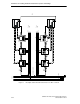
According to EN 50310 /21/, a “common bonding network CBN” with a fine mesh
of conductive elements must be created in buildings with information technology
systems. Systems that extend beyond one floor and that are interconnected by
electrical bus cables require a three-dimensional CBN with a lattice construction
resembling a Faraday cage.
With the following measures, you can create a grounding and bonding system that
will improve EMC:
S Include all the metal parts of a building in a common bonding network (CBN)
with low impedance and high current carrying capacity. To this network, you
should then connect the main grounding terminal or bar, grounding conductors,
metal conduits, reinforcing rods, equipotential bonding ring conductor, cable
racks and any additional bonding conductors.
S Connect all inactive metal parts in the immediate vicinity of your automation
components and bus cables to the bonding system ensuring good conductivity.
This includes all metal parts of cabinets, machine parts etc. that have no
electrical function in the automation system.
S Include metal, conducting cable channels/racks in the equipotential bonding of
the building and between the individual parts of the system. The individual
segments of the channels/racks must be connected together with low
inductance and low resistance and connected to the CBN system as often as
possible. Expansion joints and angled connections should be bridged by
additional flexible grounding bands. The connections between the individual
segments of channels must be protected from corrosion to ensure long-term
stability.
S The effectiveness of equipotential bonding is greater when the impedance of
the bonding conductor is low.
S The impedance of the additional bonding conductor must not exceed 10% of
the shield impedance of parallel Industrial Twisted Pair cables.
S Protect the bonding conductor from corrosion.
S Install the bonding conductor so that the area enclosed by the bonding
conductor and signal cables is as small as possible.
S Use copper or galvanized steel for the bonding conductor.
For information about grounding and bonding techniques, refer to the system
manuals of the SIMATIC S7-300 /9/, S7-400 /10/ programmable controllers.
Note
Equipotential bonding is unnecessary if the sections of a system are connected
exclusively using fiber-optic cable (FO).