SIMATIC NET Produktinformation Product Information Information produit Informazioni sul prodotto Información sobre producto C79000–Z8964–C038–05 Stand/ Dated/ Edition/ Versione/ Versiòn CP 343–1 06/99 6GK7 343-1BA00-0XE0 ab Ausgabestand 7 (FW–Stand V5.00) version 7 or higher (firmware V5.00) à partir de la version 7 (microprogramme V5.00) a partire dalla versione 7 (versione FW V4.00) a partir de la versión 7 (FW-V5.
Hinweis / Note / Avertissement / Avvertenza / Indicación Achtung Vor der Inbetriebnahme Hinweise in der entsprechenden aktuellen Dokumentation beachten. Die Bestelldaten hierfür entnehmen Sie bitte den Katalogen oder wenden Sie sich an Ihre örtliche SIEMENSĆNiederlassung. Die Inbetriebnahme ist solange untersagt, bis festgestellt wurde, daß die Maschine, in die diese Komponente eingebaut werden soll, den Bestimmungen der Richtlinie 89/392/EWG entspricht.
english Contents Notes for the Reader . . . . . . . . . . . . . . . . . . . . . . . . . . . . . . . . . . . . . . . . 2 1 The CP 343-1 Communications Processor . . . . . . . . . . . . . . . 3 1.1 1.2 1.2.1 1.2.2 1.3 1.4 Characteristics . . . . . . . . . . . . . . . . . . . . . . . . . . . . . . . . . . . . . . . . . . . . . . . Performance Data . . . . . . . . . . . . . . . . . . . . . . . . . . . . . . . . . . . . . . . . . . . . Characteristics of S7 Communication . . . . . . . . . . . . . . . . .
english Notes for the Reader Safety Guidelines This manual contains notices which you should observe to ensure your own personal safety, as well as to protect the product and connected equipment. These notices are highlighted in the manual by a warning triangle and are marked as follows according to the level of danger: Note draws your attention to particularly important information on the product, handling the product, or to a particular part of the documentation.
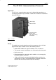
english 1 The CP 343-1 Communications Processor Application The CP 343-1 communications processor is designed for operation in an S7-300 programmable logic controller. It allows the S7-300 to be attached to Industrial Ethernet.
english Configuration You can configure the CP 343–1 via MPI or LAN/Industrial Ethernet. You require STEP 7 with the following version of NCM S7 for Industrial Ethernet (abbreviated to ”NCM IE” below): Table 1 Version STEP7/NCM IE V2.x to V5.x Functionality of the CP 343–1 The same functionality is available as with the previous versions of the CP. S Configuration data created with these STEP 7 or NCM versions can be downloaded to the CP 343–1. V5.
english Note If there is a diagnostic connection to the CP via the CPU, configuration data cannot be downloaded automatically to the CP by the CPU at the same time! Extended Functions Compared with Version 5 S Reading and writing data in the FETCH/WRITE mode The services FETCH and WRITE are supported for direct access to system memory areas on the SIMATIC S7 PLC via ISO transport and and ISO-on-TCP connections.
english Table 2 CPU MLFB–Number CPU 614 6ES7 614–1AH03–0AB3 CPU 614–Z 6ES7 614–1AH03–0AB3–Z The table lists the CPUs approved at the time of printing this product information bulletin. S7–300 CPUs approved later and not listed in the table also support the range of functions described here. All versions of the SINUMERIK CPUs 840D and 810D are supported.
english 1.2 Performance Data 1.2.1 Characteristics of S7 Communication The functions and characteristics of S7 communication are described in /8/ and /11/. 1.2.
english Table 5 Component Explanation / Values Run time in the CPU 314-1 per block AG-SEND/AG-LSEND, AG-RECV/AG-LRECV 2.5 ms to 5 ms 1.
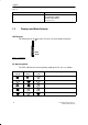
english STOP–LED (yellow) RUN–LED (green) SF–LED (red) CP operating mode Module fault / system error Legend: lit off flashing Note Read the explanations of the operating modes in the NCM S7 for Industrial Ethernet manual /8/. Controlling the Operating Mode There are three ways in which you can control the mode of the CP 343-1, as follows: S Mode selector S From a PG/PC. You can also control the modes using the configuration software in STEP 7, as follows .
english Note Read the sections about downloading configuration data to the CP in the NCM S7 for Industrial Ethernet manual /8/. 1.4 Further Information on Operation Downloading Firmware The CP 343-1 supports firmware updates using the Firmware Loader. An update of the firmware can be downloaded from the PC/programming device at any time. After downloading the firmware, the CPU must be reconfigured (power off/on or memory reset).
english Status on the FC call interface; special situation with FC versions With the FCs AG_SEND (FC 5) and AG_RECV (FC 6), you receive the following return values after a connection is aborted: S AG_SEND: DONE=1; ERROR=0; Status=0000H S AG_RECV: DONE=0; ERROR=1; Status=8183H The new FCs for longer data fields (FC AG_LSEND and AG_LRECV) react in exactly the same way to a connection abort, in other words with the return values S DONE=0; ERROR=1; Status=8183 Influence of MPI Connections on Connections via Ind
english 2.2 Procedure Steps in Installation Installing the CP 343-1 involves the following steps. S Plug in the CP 343-1 and secure it with the screws (make sure that the bus connector between the CPU/IM and CP 343-1 is present). S Attach the CP 343-1 to Industrial Ethernet as illustrated in Section 2.3. S Connect a 24 V power supply. Note Make sure that you use the same voltage source as for the CPU or IM 361. Note The two front panels must be kept closed during operation.
english 2.3 Attaching the CP 343-1 to Industrial Ethernet The CP 343-1 can be attached to Industrial Ethernet using a S Transceiver with an AUI interface CP 343–1 SF RUN STOP RUN STOP R Transceiver cable (drop cable) 727-1 Transceiver Figure 3 Attaching the CP 343-1 to Industrial Ethernet with AUI/Transceiver The CP 343-1 generates and supplies the 13 V power required by the transceiver. S Industrial Twisted Pair attachment, for example using a Optical Switch Module (OSM) or hub.
english CP 343–1 CP 343–1 SF SF e.g Optical Switch Modul (OSM) RUN STOP RUN STOP RUN STOP RUN STOP R R ITP installation cable Figure 4 Attaching the CP343-1 to Industrial Ethernet with TP/Optical Switch Module (OSM) or Hub S Optical Industrial Ethernet using an AUI attachment Connection of the CP 343-1 TCP to Industrial Ethernet is also possible using an optical transceiver with an AUI interface.
english 3 Technical Data 3.1 General Technical Data Dimensions and Weight Dimensions, module in casing H x W x D (mm) 125x80x120 Weight approx. 750 g Voltage, Current, Operating Conditions Power supply Current consumption: – from the S7-300 backplane bus: – from the external 24 V supply: Permitted ambient temperature Specifications according to /7/ must be adhered to when operating an S7-300 tier – horizontal installation – vertical installation Altitude 5 V DC +/– 5% 24 V DC +/– 5% 70 mA 0.6 A.
english 3.2 Pinout Connector for Industrial Ethernet On the front panel of the CP 343-1, there is a 15-pin sub D female connector with a sliding locking mechanism for connecting a transceiver cable. The signals of an ITP interface can also be applied to this connector (switchover by relay). For operation via the AUI interface, use the 727-1 transceiver cable. A special SIMATIC NET ITP cable must be used when operating via the ITP interface.
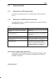
english 3.3 Notes on the CE Approval of SIMATIC NET Products Product name: CP 343-1 Order number: 6GK7 343-1BA00-0XE0 EU Directive EMC89/336/EEC The SIMATIC NET products listed above meet the requirements of the EU directive 89/336/EEC ”Electromagnetic Compatibility”.
english 4 References The following documentation is necessary for configuration and operation and contains detailed information: /7/ For installing and starting up the CP 343-1 Manual: S7-300 Programmable Controller, Hardware and Installation /8/ For using and configuring the CP 343-1 Manual: SIMATIC NET NCM for S7 Industrial Ethernet /9/ SIMATIC NET Manual: Triaxial Networks for Industrial Ethernet /10/ Ethernet Manual (HIR) /11/ User’s Guide to STEP 7 Part of the basic STEP 7 package.
C79000-Z8974-C43-01 Mail / FAX Reply (Call ++911-978-3321) From To Siemens AG, Infoservice A&D Z 032 Postfach 2348 D-90713 Fürth Germany Name ............................................................................. Position ............................................................................. Company ............................................................................. Address ............................................................................. Town ...............