
Operating instructions


Table Of Contents
- SIMATIC IPC627C
- Legal information
- Table of contents
- 1 Introduction
- 2 Safety notes
- 3 Description
- 4 Application planning
- 5 Mounting
- 6 Connecting
- 7 Commissioning
- 8 Integration
- 9 Functions
- 10 Expansion and parameter assignment
- 11 Service and maintenance
- 11.1 Removing and installing hardware components
- 11.1.1 Repairs
- 11.1.2 Preventive maintenance
- 11.1.3 Replacing the Backup Battery
- 11.1.4 Removing/Installing the Power Supply
- 11.1.5 Installing / removing the bus board
- 11.1.6 Installing / removing the motherboard
- 11.1.7 Installing / removing the equipment fan
- 11.1.8 Installing / removing the power supply fan
- 11.1.9 Processor replacement
- 11.2 Reinstalling the software
- 11.2.1 General installation procedure
- 11.2.2 Restoring the Factory State of the Software Using the Restore DVD
- 11.2.3 Installing Windows
- 11.2.4 Setting up the language selection by means of the Multilanguage User Interface (MUI)
- 11.2.5 Recovery of Windows 7
- 11.2.6 Installing drivers and software
- 11.2.7 Installing the RAID Controller software
- 11.2.8 Installing the optional burner or DVD software
- 11.2.9 Update installation
- 11.2.10 Data backup / subsequent modification of partitions
- 11.2.11 CP 1616 onboard
- 11.3 Installing the RAID Controller software
- 11.4 BIOS update
- 11.5 BIOS Recovery
- 11.1 Removing and installing hardware components
- 12 Alarm, error, and system messages
- 13 Troubleshooting/FAQs
- 14 Technical data
- 15 Dimension drawings
- 16 Detailed descriptions
- A Appendix
- B ESD guidelines
- C List of abbreviations
- Glossary
- Index
Detailed descriptions
16.1 Motherboard
SIMATIC IPC627C
138 Operating Instructions, 11/2010, A5E02669068-02
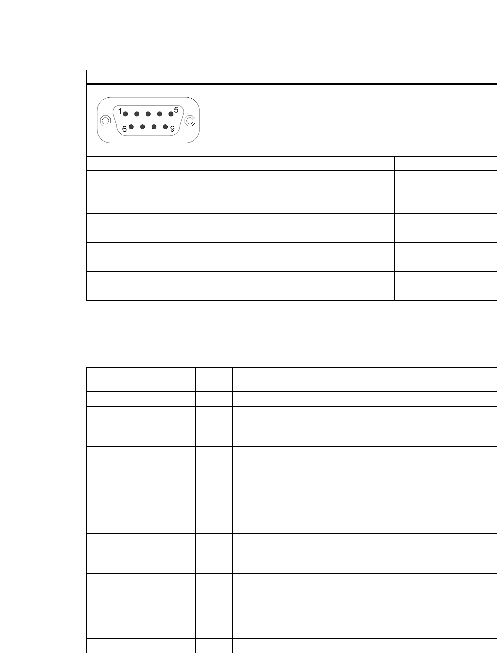
Serial interface COM 1, X30
The COM1 serial port has the following pin assignment:
Serial interface COM1
Pinno. Short description Meaning Input / Output
1 DCD (M5) Receive signal (carrier) Input
2 RxD (D2) Receive data Input
3 TxD (D1) Transmit data Output
4 DTR (S1) Data terminal ready Output
5 GND (E2) Functional ground (reference potential) –
6 DSR (M1) Ready for operation Input
7 RTS (S2) Request to send Output
8 CTS (M2) Clear to send Input
9 RI (M3) Incoming call Input
16.1.5 Internal interfaces
Pin assignment of the internal ports
Interface Positio
n
Connector Description
Memory Internal X19, X20 2 DIMM sockets, 64-bit
Bus expansion Internal X10, X610 Socket for bus expansion, assigned PCI bus
signals
Power supply Internal X13 20-pin connector plug for power supply
BIOS Recovery Internal X72
Serial ATA Internal X50, X51,
X52, X53,
X54
Serial ATA, max. 3 drives operable
Connection for PS serial
ATA
Internal X26, X27,
X28, X29,
X30
Voltage supply for serial ATA
Connection for PS fan Internal X131 Voltage supply for CPU fan, 4-pin male connector
Connection for
equipment fan
Internal X132 Voltage supply for equipment fan, 4-pin male
connector
Backup battery Internal X24, X240 Voltage supply for backup battery, 2-pin male
connector
Tap for backup battery Internal X2400 Voltage tap ( = 3V) of the backup battery,
2-pin, male connector
USB interface Internal X43 USB channel 6 and 7, 10-pole male connector
USB interface Internal X48 USB channel 9, upright USB socket