
Operating instructions


Table Of Contents
- SIMATIC IPC627C
- Legal information
- Table of contents
- 1 Introduction
- 2 Safety notes
- 3 Description
- 4 Application planning
- 5 Mounting
- 6 Connecting
- 7 Commissioning
- 8 Integration
- 9 Functions
- 10 Expansion and parameter assignment
- 11 Service and maintenance
- 11.1 Removing and installing hardware components
- 11.1.1 Repairs
- 11.1.2 Preventive maintenance
- 11.1.3 Replacing the Backup Battery
- 11.1.4 Removing/Installing the Power Supply
- 11.1.5 Installing / removing the bus board
- 11.1.6 Installing / removing the motherboard
- 11.1.7 Installing / removing the equipment fan
- 11.1.8 Installing / removing the power supply fan
- 11.1.9 Processor replacement
- 11.2 Reinstalling the software
- 11.2.1 General installation procedure
- 11.2.2 Restoring the Factory State of the Software Using the Restore DVD
- 11.2.3 Installing Windows
- 11.2.4 Setting up the language selection by means of the Multilanguage User Interface (MUI)
- 11.2.5 Recovery of Windows 7
- 11.2.6 Installing drivers and software
- 11.2.7 Installing the RAID Controller software
- 11.2.8 Installing the optional burner or DVD software
- 11.2.9 Update installation
- 11.2.10 Data backup / subsequent modification of partitions
- 11.2.11 CP 1616 onboard
- 11.3 Installing the RAID Controller software
- 11.4 BIOS update
- 11.5 BIOS Recovery
- 11.1 Removing and installing hardware components
- 12 Alarm, error, and system messages
- 13 Troubleshooting/FAQs
- 14 Technical data
- 15 Dimension drawings
- 16 Detailed descriptions
- A Appendix
- B ESD guidelines
- C List of abbreviations
- Glossary
- Index
Detailed descriptions
16.1 Motherboard
SIMATIC IPC627C
Operating Instructions, 11/2010, A5E02669068-02
135
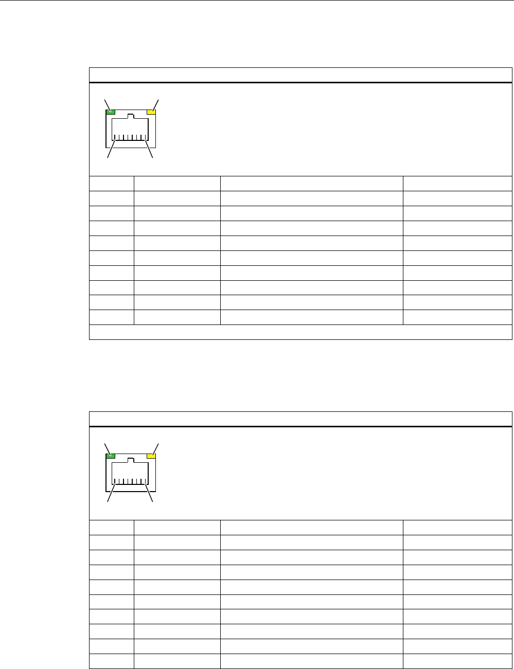
PROFINET LAN X3 Port P1, P2, P3
PROFINET interface
1
/(' /('
Pinno. Short description Meaning Input / Output
1 RD+ Receive data * Input
2 RD- Receive data * Input
3 TD+ Transmit data * Output
4, 5
1)
SYMR Internal with 75 Ohm terminating resistor _
6 TD- Receive data * Output
7, 8
1)
SYMT- Internal with 75 Ohm terminating resistor _
S Shield
LED 1 Lit green: link
LED 2 Lights up yellow: activity
* Auto negotiation and auto crossover supported
1
Optional product variant
Ethernet RJ45 connection, X1, X2
Ethernet RJ45 connection
/(' /('
Pinno. Short description Meaning Input / Output
1 BI_DA+ Bi-directional data A+ Input / Output
2 BI_DA- Bi-directional data A- Input / Output
3 BI_DB+ Bi-directional data B+ Input / Output
4 BI_DC+ Bi-directional data C+ Input / Output
5 BI_DC- Bi-directional data C- Input / Output
6 BI_DB- Bi-directional data B- Input / Output
7 BI_DD+ Bi-directional data D+ Input / Output
8 BI_DD- Bi-directional data D- Input / Output
S Shield –