
User manual


8-9
Distributed I/O System DP/ASi Link
EWA 4NEB 710 6055-02b
8.2.2 Diagnostic Fundamentals in Operations with an S7/M7 DP Master
(STEP 7) or with Another PROFIBUS-DP Master
If you are operating the DP/ASi link as a DP slave with a SIMATIC S7/M7
DP master, the DP/ASi link behaves like a central S7-300 I/O module.
You read out the diagnosis (data records 0 and 1) using SFC 13
”DPNRM_DG”. You will find information on requesting diagnostic data in
the STEP
7 Standard and System Functions manual.
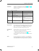
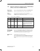
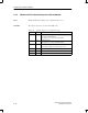
Table 8-5 Parameters for SFC 13 “DPNRM_DG”
Parameter Declaration Data Type Memory Area Description
REC INPUT BOOL I, O, M, D, L, Const. REQ = 1: Read request
LADDR INPUT WORD I, O, M, D, L, Const. Configured diagnostic address from I area of
DP/ASi link.
RET_VAL OUTPUT INT I, O, M, D, L If an error occurs while the function is being
processed, the return value contains an error
code. If an error does not occur, the length of
the data actually transferred is located in
RET_VAL.
RECORD OUTPUT ANY I, O, M, D, L Destination area for diagnostic data after being
read. Only data type BYTE is allowed.
BUSY OUTPUT BOOL I, O, M, D, L BUSY = 1: Read process continuing.
If you operate the DP/ASi link as a DP slave with a DP master from Siemens
that is not part of the SIMATIC S5/S7/M7 PLCs or with a DP master from
another manufacturer, please refer to the documentation for the DP master
concerned for the way in which the slave diagnosis is requested.
The DP/ASi link supports diagnostic interrupts.
You can evaluate these interrupts using an S7/M7 DP master. Should an inter-
rupt occur, interrupt OBs are processed automatically by the CPU (refer to
the System Software for S7-300 and S7-400, Program Design programming
manual).
Diagnosis with
S7/M7 DP Master
SFC 13
“DPNRM_DG”
Diagnosing with
other PROFIBUS-
DP masters
Diagnostic inter-
rupts
Diagnostics and Error Handling