
User manual

8-2
Distributed I/O System DP/ASi Link
EWA 4NEB 710 6055-02b
8.1 Diagnostics by Means of LEDs of DP/ASi Link
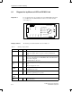
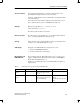
For on-site diagnostics, the operating modes of the DP/ASi link are displayed
by six LEDs. Five other LEDs indicate the address of the failed ASi slave
(refer to Fig. 8-1).
DP / ASi LINK
CONFIG ERROR
AUTOPROG AV
CONFIG MODE
ASi POWER FAIL
RUN BF
124816+ + + + = ASi SLAVE FAIL
+ PS
L2 DP
SINEC
+ 1
3
ASi
6ES7 156-0AA01-0XA0
123456
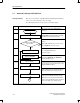
Figure 8-1 Location of LEDs of DP/ASi link
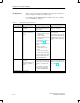
The meanings of the different LEDs is shown in Table 8-1.
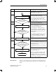
Table 8-1 Meanings of display LEDs
Name Color State Function
RUN Green On
Off
24 V power supply is in order.
24 V power supply is either not present or below permitted limit
value.
BF Red On
Off
Response monitoring has terminated or parameters have not been as
signed yet to DP/ASi link for the PROFIBUS-DP and the DP/ASi link
has not been configured.
PROFIBUS-DP is in data cycle.
ASi POWER
FAIL
Red On
Off
ASi power supply is either not present or below the permitted limit
value.
ASi power supply is in order.
CONFIG
ERROR
Yellow On
Off
Configuration error on ASi
Configuration is in order
AUTPROG
AV
Green On
Off
Automatic programming is possible.
Automatic programming is not possible.
CONFIG
MODE
No function
ASi SLAVE
FAIL
Red These five LEDs are used to indicate the failed ASi slave with the
lowest ASi address.
Diagnostics
Display elements
Diagnostics and Error Handling