
User manual

5-10
Distributed I/O System DP/ASi Link
EWA 4NEB 710 6055-02b
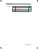
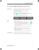
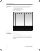
The table below describes the location of ASi data in the input and output
area. A specific address is permanently assigned to every ASi slave:
even-numbered ASi slaves: bits 4 to 7
odd-numbered ASi slaves: bits 0 to 3
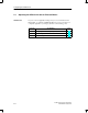
Table 5-2 I/O area assignment
Input and Output
Byte Bit 7 Bit 6 Bit 5 Bit 4 Bit 3 Bit 2 Bit 1 Bit 0
n Slave 1
n + 1 Slave 2 Slave 3
n + 2 Slave 4 Slave 5
n + 3 Slave 6 Slave 7
n + 4 Slave 8 Slave 9
n + 5 Slave 10 Slave 11
n + 6 Slave 12 Slave 13
n + 7 Slave 14 Slave 15
n + 8 Slave 16 Slave 17
n + 9 Slave 18 Slave 19
n + 10 Slave 20 Slave 21
n + 11 Slave 22 Slave 23
n + 12 Slave 24 Slave 25
n + 13 Slave 26 Slave 27
n + 14 Slave 28 Slave 29
n + 15 Slave 30 Slave 31
Should you wish to modify the ASi configuration, you must keep to the follo-
wing procedure:
1. Add or remove ASi slaves.
2. Perform a new default start-up.
As soon as the DP/ASi link receives the parameterization message from the
DP master, ASi slaves that are added or removed after this point of time are
ignored. ASi slaves that have been removed are reported as having failed in
the diagnosis.
Input and output
area
Subsequent
modification of
ASi configuration
Configuring the DP/ASi Link