
User manual


4-9
Distributed I/O System DP/ASi Link
EWA 4NEB 710 6055-02b
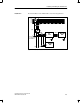
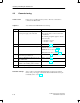
You can connect either the PROFIBUS-DP or the power supply to the device
connector. The two 12-pin connectors are interconnected internally. Table 4-3
shows the assignment of the 12-pin device connector.
Table 4-3 Pin assignment of 12-pin device connector
Pin
Assign-
ment
Meaning View
1 – Reserved
2 A
1
Data line P
3 – Reserved
4 B
2
Data line N
5 – Reserved
6 – Reserved
7 P24V 24 V input voltage
8 M24V 24 V reference poten-
tial
9 PI Protective conductor
10 – Reserved
View: mating side
11 – Reserved
12 – Reserved
1
Green on Siemens sourced cable
2
Red on Siemens sourced cable
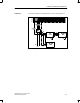
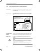
You connect the power supply to the DP/ASi link using the second device
connector. Make sure that the power supply cable is deenergized at the time
of connection.
!
Warning
The DP/ASi link may be destroyed by voltage glitches that may occur while
the connector is being slipped on.
The DP/ASi link starts up automatically when the operating voltage is turned
on.
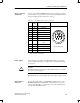
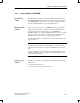
If you run the supply voltage over the PROFIBUS-DP and do not loop the
PROFIBUS-DP through the DP/ASi link, you must seal the second device
connector with the metal cap or, if necessary, screw on the terminating resis-
tor. Only then is IP 66/IP 67 assured.
Device connector
assignment
Power supply
Unused device
connector
Installing and Wiring the DP/ASi Link