
User manual

3-6
Distributed I/O System DP/ASi Link
EWA 4NEB 710 6055-02b
3.4 Configuration with Several Power Supply Connectors
In configurations with a power supply connector (refer to sections 3.2 and
3.3), the power supply is fed along the bus cable.
This configuration is limited by the following factors:
If the power supply and the PROFIBUS-DP field bus are fed on the same
cable, the following values apply to the length of the bus cable between
the power supply connector and the last slave station connected:
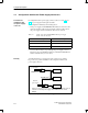
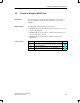
Table 3-2 Length of bus cable when PROFIBUS-DP and power supply
are fed on the same bus cable
Current Loading Max. Cable Length
< 1 A 80 m
< 2 A 40 m
< 4 A 20 m
Not more than 4 A may be looped through the power supply connector.
The input power of the ET 200 modules and of the DP/ASi link limits the
number of modules that you can connect.
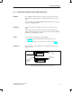
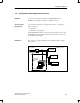
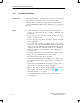
You make allowance for several power supply connectors per segment.
Fig. 3-5 shows a possible installation for the configuration with several
power supply connectors.
SV
External
power supply
PROFIBUS-DP
PS-
cntr
PS
External
power supply
PROFIBUS-DP
1
PS-
cntr
1
In this case you can use a 2- or 5-core cable, because the two ”left” con-
nections for ”external power supply” and ”PROFIBUS-DP” are not
bridged.
DP/ASi link
DP/ASi link
DP/ASi link
Figure 3-5 Configuration with several power supply connectors
Constraint for
installation with
one power supply
connector
Remedy
Configuration Options