
User manual


2-5
Distributed I/O System DP/ASi Link
EWA 4NEB 710 6055-02b
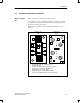
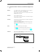
2.3 Example Configuration of a Module
Every module consists of an upper part and a lower part.
As an example, you can see an illustration in Fig. 2-2 of an upper part with
two inputs and two outputs and a lower part for the ASi cable without an in-
terface for an external power supply.
The upper part is attached to the lower part with four attaching screws (see
remark g).
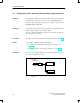
a
b
a
Contact spikes with two contacts per core
b
ASi cable aperture
c
Seals for the cable apertures that are not required
d
Actuator/sensor connection with M12 bush
e
Display LEDs for input and output
f
Drilled through-hole for attaching the module
g
Screws for attaching the upper part to the lower part
c
O4
I1
O3
I2
d
e
f
g
Module lower
part
Module upper
part
Figure 2-2 View of module, example of an upper part and a lower part
Module configura-
tion
ASi Basics