
User manual


D-7
Distributed I/O System DP/ASi Link
EWA 4NEB 710 6055-02b
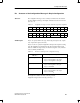
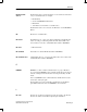
D.3 Structure of the Configuration Message in Simple Configuration
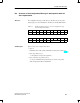
The configuration message consists of 20 bytes and must have the structure
shown in Table D-5. The type and length of the I/O area used are encoded in
bytes 15 to 17.
Table D-5 Configuration message for masters with reduced parameter assignment
Byte 0 1 2 3 4 5 6 7 8 9
Value 04
H
00
H
00
H
AD
H
C0
H
04
H
00
H
00
H
BB
H
40
H
Byte 10 11 12 13 14 15 16 17 18 19
Value 04
H
00
H
00
H
8F
H
C0
H
variable 3C
H
40
H
In byte 15, specify an ID for the type of I/O being used (inputs only, outputs
only or inputs and outputs connected).
In bytes 16 and 17, specify the length ID for the input and output areas being
used. The length IDs are determined by the slaves having the highest ASi
addresses. Make sure that precisely one nibble is assigned to every ASi slave
(refer to summary in Table D-6).
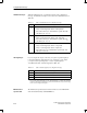
Table D-6 IDs for the variable part of the configuration message
Connected to the DP/ASi
Link Are ...
The Configuration Message Must Contain:
Inputs and outputs in byte 15, the ID C2
H
in byte 16, the length ID for the outputs
in byte 17, the length ID for the inputs
Inputs only in byte 15, the ID 43
H
in byte 16, the length ID for the inputs
in byte 17, the ID 00
H
Outputs only in byte 15, the ID 83
H
in byte 16, the length ID for the outputs
in byte 17, the ID 00
H
The length ID is calculated from the following formula:
Length ID = Length of I/O area being used in byte – 1
Structure
Variable bytes
Configuration Message