
User manual


C-7
Distributed I/O System DP/ASi Link
EWA 4NEB 710 6055-02b
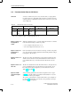
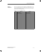
In Table C-7 you will find the assignment of the ASi addresses to the byte
numbers within the parameterization message.
Table C-7 Assignment of parameterization data of ASi slaves to byte numbers of
parameterization message
Parameterization Data for ASi Slave with
ASi Address
... Assigned to Bytes
1 16 to 19
2 20 to 23
3 24 to 27
4 28 to 31
5 32 to 35
31 136 to 139
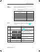
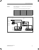
The way in which you determine the value of an input or output byte is
shown in the table below. ASi slave No. 4, as defined in Fig. C-1, is used in
the example.
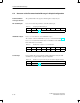
Step Action Explanation
1
Byte number:
1
Bit number: 0
Take the byte number (1) and the bit num-
ber (0) from the address space template (refer
to Fig. C-1).
2
10000 000
0204Bit No.
Convert the byte number into a 5-digit binary
number and the bit number into a 3-digit
binary number. You will obtain the byte num-
ber 00001
B
and the bit number 000
B
.
3
10000 000
0237Bit No.
Merge the two binary numbers. The bit num-
ber is sorted into the position of bits 0 to 2 and
the byte number into the position of bits 3 to 7.
4
00010000
Divide the eight bits you obtain at the center
into two groups of four bits.
5
0
H
8
H
Convert both of the two groups into a hexade-
cimal number.
6
08
H
Unite the two hexadecimal numbers.
Address
assignment
Example
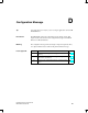
Parameterization Message