
User manual


C-4
Distributed I/O System DP/ASi Link
EWA 4NEB 710 6055-02b
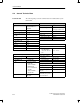
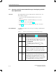
Bytes 7 to 14 are referred to as the initialization bytes.
You can modify byte 7 (refer to Table C-3), the first byte of the eight initiali-
zation bytes, as follows:
Table C-3 Structure of byte 7 for initialization
Bit(s) Meaning Value
0 Start bit monitoring 0 Monitoring is enabled
1 Monitoring is disabled
1 Stop bit monitoring 0 Monitoring is enabled
1 Monitoring is disabled
2 Watchdog time base 0 Time base = 10 ms
1 Time base = 1 ms
1
3 to 5 0 In all cases
6 0 In all cases
7 0 In all cases
1
The time base = 1 ms may be used only for transmission rates u1.5 MBd.
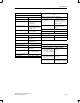
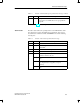
The remaining bytes (byte 8 to byte 14) are pre-defined and cannot be modi-
fied. The values of these bytes are defined in Table C-4. If you modify these
values, the DP/ASi link cannot be operated.
Table C-4 Default values of bytes 8 to 14 for initialization
Byte 8 9 10 11 12 13 14
Value 00
H
00
H
82
H
51
H
04
H
8A
H
7D
H
The control byte (byte 15) contains the other interface parameters. The con-
trol byte has the value shown in Table C-5.
Table C-5 Value of control byte (byte 15)
Value Meaning
00
H
Actual is equal to setpoint configuration
01
H
Actual is less than or equal to setpoint configuration
”Actual is equal to setpoint configuration” means that the DP/ASi link starts
up only when the actual configuration is the same as the setpoint configura-
tion. If there are any differences between the actual and setpoint configura-
tions, the DP/ASi link requests a new parameterization message.
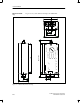
Initialization bytes
Control byte
Actual equal to
setpoint
configuration
Parameterization Message