
User manual


C-2
Distributed I/O System DP/ASi Link
EWA 4NEB 710 6055-02b
C.1 Structure of the Parameterization Message in Configuring with Ad-
dress Optimization
The parameterization message contains 140 bytes of data, bytes 0 to 139.
These 140 bytes comprise:
7 bytes in accordance with the DP standard, bytes 0 to 6, refer to
Table C-1
8 bytes for initialization of the DP/ASi link, bytes 7 to 14, refer to
Table C-4
a control byte, byte 15, refer to Table C-5
4 bytes in each case for a possible ASi slave, bytes 16 to 139, refer to
Table C-6
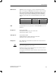
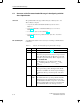
You will find the structure of the seven bytes conforming to the DP standard
in Table C-1.
Table C-1 Structure of the DP standard part in parameterization message
Byte(s) Value Meaning
0 Station status, refer to Table C-2
1 0 to 255
Watchdog factor
These two bytes represent two factors for response moni-
toring. If the DP master fails, the DP slave is reset at the
end of the response time (T
WD
). All the outputs are set to
0 b h DP/ASi li k
2 0 to 255
0 by the DP/ASi link.
You calculate the response time from the formula:
T
WD
+watchdog time base
1
factor 1
(byte 1)
fac-
tor 2
(byte 2)
3 0 to 255 Response delay
The response delay specifies the length of time the DP
slave has to wait until it can send its response message to
the DP master. The response time depends on the baud
rate.
4, 5 32795 =
801B
H
Manufacturer ID
The manufacturer ID is a product-specific ID. The DP/
ASi link accepts in the parameterization message only
that manufacturer ID which corresponds to its own. If the
ID in the parameterization message is not identical with
that of the DP/ASi link, an error message is issued.
Structure
DP standard part
Parameterization Message