
User manual

8-21
Distributed I/O System DP/ASi Link
EWA 4NEB 710 6055-02b
8.2.9 Diagnostics for a Default Start-Up with the IM308C
(6ES7 156 0AA00-0XA0 or Later, Issue 3)
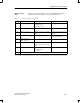
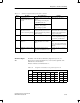
For the default start-up, the diagnostic message contains 32 bytes of data and
complies with the PROFIBUS DP standard. The table below describes the
basic structure of the diagnostic message.
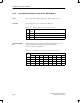
Table 8-19 Basic structure of diagnostic message
Byte(s) Contents Meaning
0 02
H
Station status 1
1 05
H
Station status 2
2 00
H
Station status 3
3 FF
H
Station number, DP Master
4 80
H
Manufacturer ID (801B
H
)
5 1B
H
6 1A
H
Header and length of module diagnosis
7 01
H
Module diagnosis
8 04
H
Header and length of first station diagnosis
9 00
H
Length of S7 area
10 22
H
Part 2 of diagnostic data
11 00
H
12 to 15 See Table
8-20
Part 1 of diagnostic data
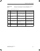
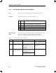
16 to 31 See Table
8-21
Actual configuration of ASi installation
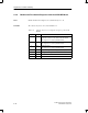
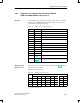
Diagnostic bytes 12 to 15 indicate an ASi slave failure. Table 8-16 shows the
assignment of the ASi addresses.
Failed ASi slaves are marked ”1”.
Table 8-20 Indication of failed ASi slaves
Byte
Bit (Corresponds to ASi Address)
7 6 5 4 3 2 1 0
12 7 6 5 4 3 2 1 *
13 15 14 13 12 11 10 9 8
14 23 22 21 20 19 18 17 16
15 31 30 29 28 27 26 25 24
* Byte 12.0 is not assigned.
Structure
Diagnostic data
(bytes 12 to 15)
Diagnostics and Error Handling