
User manual

8-20
Distributed I/O System DP/ASi Link
EWA 4NEB 710 6055-02b
8.2.8 Second Station Diagnosis with the S7/ M7 DP Master
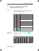
The second part of the station diagnosis is contained in bytes 17 to 23.
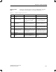
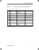
The contents of bytes 17 to 19 are shown in Table 8-17.
Table 8-17 Structure of bytes 17 to 19 in diagnostic message
Byte Con-
tents
Contents
17 60
H
Channel type (channel module)
18 00
H
Length of overall diagnostic information per channel
19 20
H
Number of channel modules
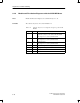
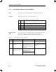
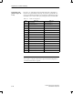
Diagnostic bytes 20 to 23 indicate an ASi slave failure. In Table 8-18, you
will see the assignment of the different bits to the ASi address.
Erroneous ASi slaves are marked ”1”.
Table 8-18 Assignment of the ASi address to bit positions, bytes 20 to 23
Byte
Bit (Corresponds to ASi Address)
7 6 5 4 3 2 1 0
20 7 6 5 4 3 2 1
1
21 15 14 13 12 11 10 9 8
22 23 22 21 20 19 18 17 16
23 31 30 29 28 27 26 25 24
1
This position is not assigned.
Area
Contents
ASi slave diagno-
sis
Diagnostics and Error Handling