
User manual

8-18
Distributed I/O System DP/ASi Link
EWA 4NEB 710 6055-02b
8.2.7 Second Station Diagnosis with the IM308C
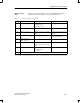
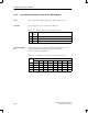
The second part of the station diagnostics is contained in bytes 16 to 25.
The contents of bytes 16 to 19 are shown in Table 8-14.
Table 8-14 Structure of bytes 16 to 19 in diagnostic message
Byte Con
tents
Contents
16 0A
H
Second station diagnostics with 10 bytes including header.
The second station diagnostics covers bytes 16 to 25.
17 xx
H
This area has been prepared for an extended diagnosis from your S7.
18 04
H
Reserved
19 00
H
Reserved
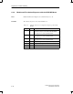
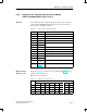
The second part of the station diagnostic data of the DP/ASi link, which refer
to the ASi, are spread over two areas. In the first area, as shown in
Table 8-15, you will find ASi-related data. A message is indicated by a ”1”.
Table 8-15 Structure of diagnostic data, bytes 20 and 21
Byte
1
Meaning Reason/Reaction Remedy
20.1 ASi power supply ASi power supply has failed. Check the ASi power supply.
Check the connections of the ASi.
20.4 Automatic programming is
possible.
Precisely one ASi slave has failed
(refer to sec tion 7.3).
The address of the failed ASi slave
is indicated by five ASi SLAVE
FAIL LEDs.
Replace the failed ASi slave with a
new ASi slave having identical I/O
and ID codes.
21.0 Configuration error:
Unconfigured ASi slaves pre-
sent
On start-up:
Data exchange cannot take place
on PROFIBUS-DP side.
Remove unconfigured ASi slaves.
In operation:
Data exchange is possible.
1
Unnamed bits are without significance.
Area
Contents
Diagnostic data
Part 2
Diagnostics and Error Handling