
User manual

8-17
Distributed I/O System DP/ASi Link
EWA 4NEB 710 6055-02b
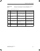
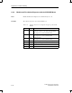
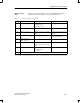
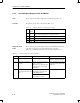
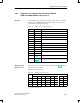
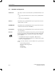
The first part of the station diagnostic data of the DP/ASi link as a DP slave
is structured as shown in Table 8-13. A message is indicated by a ”1”.
Table 8-13 Structure of diagnosis, bytes 13 to 16
Byte
1
Meaning Reason/Reaction Remedy
13.0 Module malfunction Group error
0 – Interrupt going
1 – Interrupt coming
Refer to other diagnostic data
13.2 External fault Slave failed Check and, if necessary, replace
slave
13.3 Channel error present Difference from setpoint configu-
ration
Compare setpoint and actual confi-
gurations
13.4 No external standby supply No ASi power supply. Check ASi power supply.
Check ASi connections.
14.0 to 3 Module class: 0110
(Misc. module)
– –
15.0 User module wrong/missing Configuration error: incorrect I/O
code, incorrect ID code (start-up
only)
Check I/O and ID codes
15.2 RUN/STOP mode Modes:
0 – Normal mode
1 – Offline
–
16 No meaning
1
Unnamed bits are without significance
Diagnostic data
Part 1
Diagnostics and Error Handling